APEX™ Exciter Incorporating FLO™ Technology
Details of the Exciter Status Screens Navigating the LCD Display Screens
2604s300.fm
03/08/07 888-2604-001 Page: 3-19
WARNING: Disconnect primary power prior to servicing.
3.4.5 IF & RF Processing Status Screens
The IF & RF Processing Status selection contains four sub screens, which are:
• UDC Interface Board, Screen 1 of 4
• PLL Board, Screen 2 of 4.
• Up Converter Board, Screen 3 of 4.
• Down Converter Board, Screen 4 of 4.
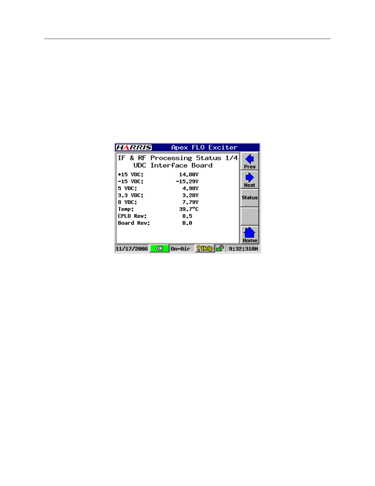
3.4.5.1 UDC Interface Board Status, Screen 1/4
UDCInterfaceStatus.bmp
Figure 3-17 UDC Interface Board Status, Screen 1/4
The UDC Interface Board screen is shown in Figure 3-17, with screen entries listed below.
• 15 Vdc: Input from power supply module
• -15 Vdc: Input from power supply module
• 5 Vdc: Output from 5 volt linear regulator chip U4.
• 3.3 Vdc: Output from 3.3 volt linear regulator chip U6.
• 8 Vdc: Output from 8 volt switching regulator
• Temp: This is the ambient air temperature inside the analog (top) side of the exciter.
• CPLD Rev: This is the revision level of the CPLD in the UDC Interface board.
• Board Rev: This is the board revision for the UDC Interface board.

 Loading...
