APEX™ Exciter Incorporating FLO™ Technologyr
APEX Exciter Analog Assembly Overview Theory of Operation
2604s400.fm
03/08/07 888-2604-001 Page: 4-13
WARNING: Disconnect primary power prior to servicing.
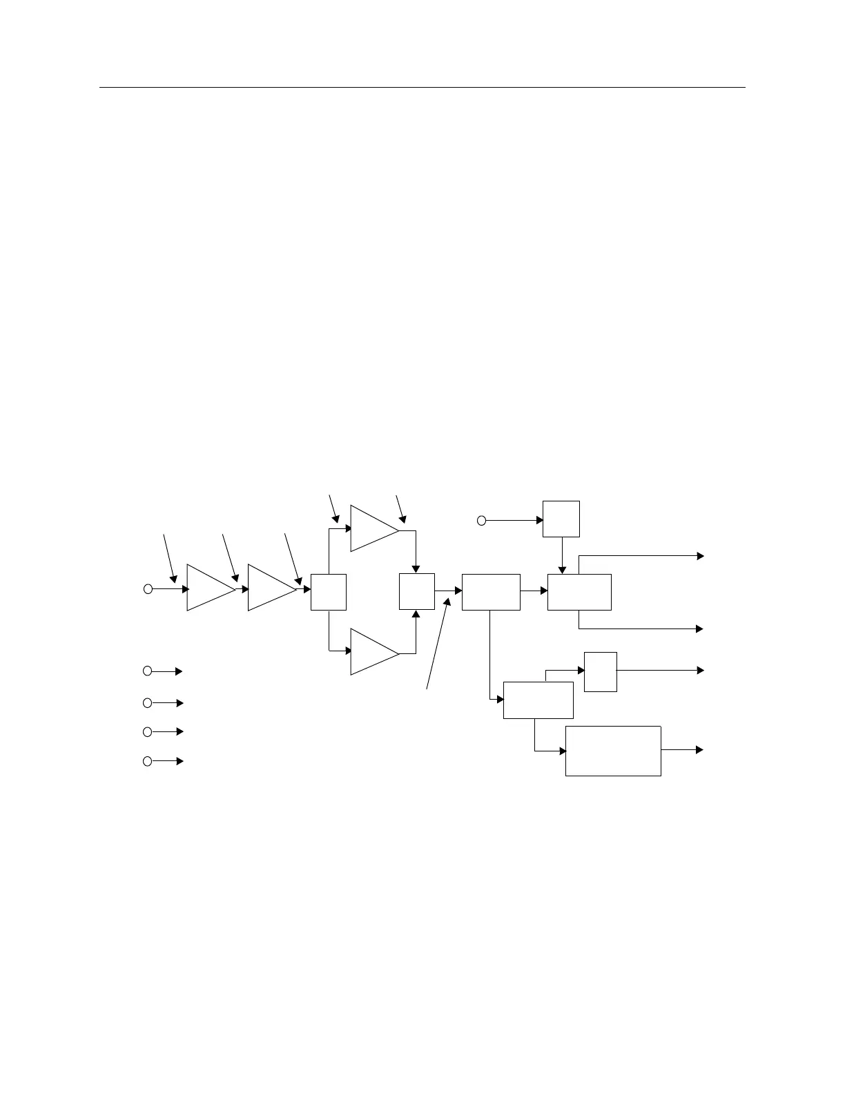
4.4.4 Output Amplifier
The output amplifier accepts an on channel input from the up converter and amplifies the
signal up to 100 mW average power. It is broad band and covers the VHF and UHF bands.
The output of the up converter is a low level signal of approximately -11 dBm. The output
amplifier provides approximately 31 dB gain to raise the signal level to +20 dBm, which is
100 mW average power (1 watt peak power).
RF input is routed from J1 through broad band amplifiers U2 and U4 and to splitter U3.
The two outputs of splitter U3 drive two broadband amplifiers U6 and U1 in parallel. The
outputs from these two amplifiers are combined in U5. From U5 the RF is routed through
directional coupler DC1 then to relay K1, which routes the output to the RF output jack (J2)
when the exciter is unmuted, and to the RF load output jack (J3) when muted.
Directional coupler DC1 samples the forward power of the amplifier and routes the sample
to splitter U7. One output of U7 drives the detector, which consists of CR3, CR6, U8, U9,
and U10. The detection diode CR3 is temperature compensated by CR6 in summing
amplifier U9. The dc output of U9 is routed to controller board via the UDC interface
board. It is used for APC (automatic power control) of the exciter RF output. The other
output of U7 is routed through a 7 dB attenuator (R26, R27, and R29) and provides a 2
dBm RF sample for the exciter input of the down converter board.
Figure 4-10 Output RF Amplifier Block Diagram
U2
U4
U3
U5
U1
U6
DC1
Coupler
U7 Splitter
Q1
K1 Relay
CR3, CR5, U8,
U9, and U10
Detector
J5-7
Input
-11dBm +7dBm +17dBm
RF Output
To PA
+24 dBm
RF Output
to Load
+24 dBm
RF Sample
+2dBm
J5-8
Detector
Output
J2
J3
J4
Mute
J5-1
J5-2
J5-3
J5-4
+15Vdc Input
Ground
-15Vdc Input
Ground
J1
RF Input
+13dBm
+23dBm
+25dBm
7dB
Att.
(at approx. 1665 mA)
(at approx 5 mA)

 Loading...
