 Loading...
Do you have a question about the HEIDENHAIN TNC 430 CA and is the answer not in the manual?
| Manufacturer | HEIDENHAIN |
|---|---|
| Resolution | 640 x 480 pixels |
| Number of Axes | Up to 5 |
| Interpolation | Linear, circular, helical, spline |
| Power Supply | 24 V DC |
| Operating Temperature | 0 to 45 °C |
| Control Unit Type | CNC |
| Display | Color TFT |
| Interfaces | RS-232, USB, Ethernet |
| Protection Class | IP20 |
Overview of HEIDENHAIN TNC CNC controls, their capabilities, and programming features.
Procedure for safely powering on and off the TNC control and machine tool.
Methods for traversing machine axes manually using direction buttons or electronic handwheels.
Procedures for setting workpiece datums, with and without a touch probe.
Using MDI mode for simple operations, short programs, and immediate execution.
Basic principles of NC, including position encoders, reference marks, and coordinate systems.
Basic concepts of file management, including file types, names, and data security.
Steps for organizing, defining, and creating NC part programs.
Displaying and interpreting error messages with detailed explanations and correction suggestions.
Inputting and managing feed rate (F) and spindle speed (S) for tools.
Entering tool length (L), radius (R), and delta values for tool compensation.
Adjusting spindle path for tool length and compensating for tool radius in the working plane.
Carrying out 3-D tool compensation for straight-line blocks using surface-normal vectors.
Utilizing cutting data tables for automatic calculation of spindle speed and feed rate.
Programming tool movements for workpiece machining using basic path functions.
Functions for approaching and departing contours with straight lines and circular arcs.
Defining contour elements using Cartesian coordinates like lines, chamfers, circles, and rounding.
Defining positions and contours using polar coordinates with angle and distance.
Programming contours with limited or unconventional coordinate data using FK function.
Using M functions to control program run, machine functions, and contouring behavior.
Functions for controlling program execution, spindle rotation, and coolant supply.
Functions for smoothing corners, machining steps, open contours, and feed rate adjustments.
Overview of standard and special cycles, their structure, and calling methods.
Detailed explanation of drilling cycles like PECKING, DRILLING, REAMING, BORING, and TAPPING.
Cycles for milling rectangular and circular pockets, studs, and slots.
Cycles for creating circular and linear patterns of holes.
Cycles for contour-oriented machining of complex contours and achieving high surface finish.
Cycles for shifting, mirroring, rotating, scaling, and tilting contours.
Operating sequence and programming notes for using subprograms within a main program.
Introduction to Q parameters for variable programming and contour definition.
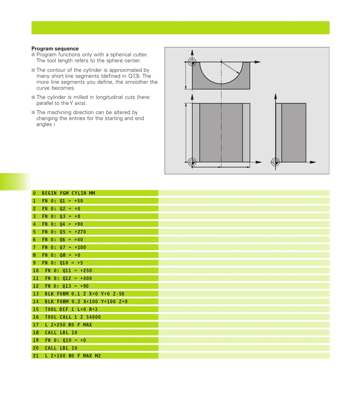
Using Q parameters to program entire families of parts by defining characteristic dimensions.
Using Q parameters and basic mathematical functions for contour programming.
Making logical decisions in programs based on Q parameter comparisons.
Display modes for workpiece graphics: Plan, 3-plane projection, and 3-D view.
Simulating programs and sections to detect errors, including geometrical incompatibilities and data issues.
Procedures for testing entire programs or individual blocks, including error handling.
Executing part programs in Full Sequence or Single Block mode.
Methods to interrupt program run, including programmed interruptions and machine stop button.
Accessing and modifying settings within the MOD functions based on operating mode.
Configuration of RS-232, RS-422, and Ethernet interfaces for data transfer.
Connecting the TNC to a network via Ethernet, including software requirements and connection possibilities.
Pin assignments for RS-232-C/V.24, RS-422/V.11, and Ethernet interfaces.
Categories of fixed cycles for drilling, milling, hole patterns, and surface interpolation.
Functions for datum shift, mirroring, rotation, scaling, and tilting the working plane.
Technical specifications including block processing time, control loop cycle time, and data transfer rates.