EasyManua.ls Logo

HEIDENHAIN TNC 430 CA User Manual

HEIDENHAIN TNC 430 CA
362 pages
To Next Page IconTo Next Page
To Previous Page IconTo Previous Page
Page #76 background imageLoading...
Page #76 background image
60
4 Programming: Fundamentals of NC, File Management,
Programming Aids, Pallet Management
4.9 Creating Text Files
You can use the TNC’s text editor to write and edit texts. Typical
applications:
Recording test results
Documenting working procedures
Creating formularies
Text files are type .A files (ASCII files). If you want to edit other
types of files, you must first convert them into type .A files.
Opening and exiting text files
ú
Select the Programming and Editing mode of operation.
ú
To call the file manager, press the PGM MGT key.
ú
To display type .A files, press the SELECT TYPE and then the
SHOW .A soft keys.
ú
Select a file and open it with the SELECT soft key or ENT key,
or create a new file by entering the new file name and confirming
your entry with the ENT key.
To leave the text editor, call the file manager and select a file of a
different file type, for example a part program.
Editing texts
The first line of the text editor is an information headline which
displays the file name, and the location and writing mode of the
cursor:
File: Name of the text file
Line: Line in which the cursor is presently located
Column: Column in which the cursor is presently located
Insert: Insert new text, pushing the existing text to the
right
Overwrite: Write over the existing text, erasing it where it is
replaced with the new text.
The text is inserted or overwritten at the location of the cursor. You
can move the cursor to any desired position in the text file by
pressing the arrow keys.
The line in which the cursor is presently located is depicted in a
different color. A line can have up to 77 characters. To start a new
line, press the RET key or the ENT key.
4.9 Creating Text Files
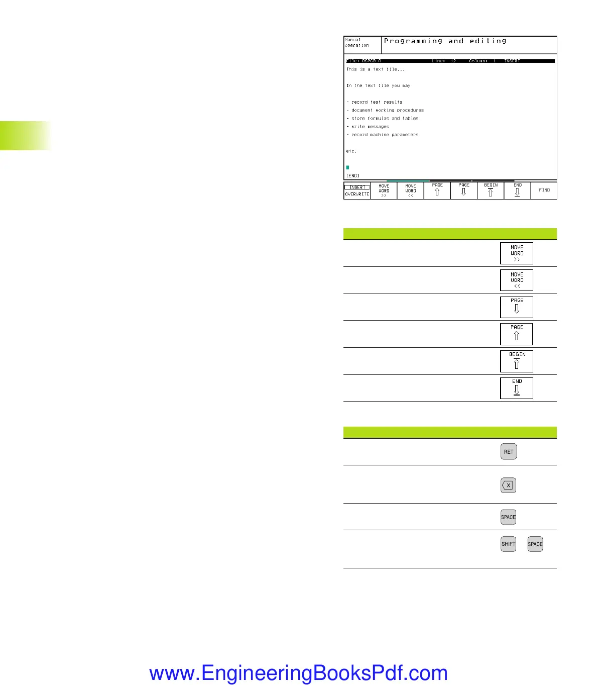
Cursor movements Soft key
Move one word to the right
Move one word to the left
Go to the next screen page
Go to the previous screen page
Go to beginning of file
Go to end of file
Editing functions Key
Begin a new line
Erase the character to the left
of the cursor
Insert a blank space
Switch between upper and lower +
case letters
Ekap4.pm6 30.06.2006, 07:0360
www.EngineeringBooksPdf.com

Table of Contents

Other manuals for HEIDENHAIN TNC 430 CA

Question and Answer IconNeed help?

Do you have a question about the HEIDENHAIN TNC 430 CA and is the answer not in the manual?

HEIDENHAIN TNC 430 CA Specifications

General IconGeneral
ManufacturerHEIDENHAIN
Resolution640 x 480 pixels
Number of AxesUp to 5
InterpolationLinear, circular, helical, spline
Power Supply24 V DC
Operating Temperature0 to 45 °C
Control Unit TypeCNC
DisplayColor TFT
InterfacesRS-232, USB, Ethernet
Protection ClassIP20

Summary

Introduction

The TNC 426 B, the TNC 430

Overview of HEIDENHAIN TNC CNC controls, their capabilities, and programming features.

Manual Operation and Setup

Switch-on, Switch-off

Procedure for safely powering on and off the TNC control and machine tool.

Moving the Machine Axes

Methods for traversing machine axes manually using direction buttons or electronic handwheels.

Setting the Datum

Procedures for setting workpiece datums, with and without a touch probe.

Positioning with Manual Data Input (MDI)

Programming and Executing Simple Machining Operations

Using MDI mode for simple operations, short programs, and immediate execution.

Programming: Fundamentals of NC, File Management, Programming Aids, Pallet Management

Fundamentals of NC

Basic principles of NC, including position encoders, reference marks, and coordinate systems.

File Management: Fundamentals

Basic concepts of file management, including file types, names, and data security.

Creating and Writing Programs

Steps for organizing, defining, and creating NC part programs.

HELP for NC Error Messages

Displaying and interpreting error messages with detailed explanations and correction suggestions.

Programming: Tools

Entering Tool-Related Data

Inputting and managing feed rate (F) and spindle speed (S) for tools.

Tool Data

Entering tool length (L), radius (R), and delta values for tool compensation.

Tool Compensation

Adjusting spindle path for tool length and compensating for tool radius in the working plane.

Three-Dimensional Tool Compensation

Carrying out 3-D tool compensation for straight-line blocks using surface-normal vectors.

Working with Cutting Data Tables

Utilizing cutting data tables for automatic calculation of spindle speed and feed rate.

Programming: Programming Contours

Fundamentals of Path Functions

Programming tool movements for workpiece machining using basic path functions.

Contour Approach and Departure

Functions for approaching and departing contours with straight lines and circular arcs.

Path Contours — Cartesian Coordinates

Defining contour elements using Cartesian coordinates like lines, chamfers, circles, and rounding.

Path Contours — Polar Coordinates

Defining positions and contours using polar coordinates with angle and distance.

Path Contours — FK Free Contour Programming

Programming contours with limited or unconventional coordinate data using FK function.

Programming: Miscellaneous Functions

Entering Miscellaneous Functions M and STOP

Using M functions to control program run, machine functions, and contouring behavior.

Miscellaneous Functions for Program Run Control, Spindle and Coolant

Functions for controlling program execution, spindle rotation, and coolant supply.

Miscellaneous Functions for Contouring Behavior

Functions for smoothing corners, machining steps, open contours, and feed rate adjustments.

Programming: Cycles

General Information on Cycles

Overview of standard and special cycles, their structure, and calling methods.

Drilling Cycles

Detailed explanation of drilling cycles like PECKING, DRILLING, REAMING, BORING, and TAPPING.

Cycles for milling pockets, studs and slots

Cycles for milling rectangular and circular pockets, studs, and slots.

Cycles for Machining Hole Patterns

Cycles for creating circular and linear patterns of holes.

SL Cycles

Cycles for contour-oriented machining of complex contours and achieving high surface finish.

Coordinate Transformation Cycles

Cycles for shifting, mirroring, rotating, scaling, and tilting contours.

Programming: Subprograms and Program Section Repeats

Subprograms

Operating sequence and programming notes for using subprograms within a main program.

Programming: Q Parameters

Principle and Overview

Introduction to Q parameters for variable programming and contour definition.

Part Families — Q Parameters in Place of Numerical Values

Using Q parameters to program entire families of parts by defining characteristic dimensions.

Describing Contours Through Mathematical Functions

Using Q parameters and basic mathematical functions for contour programming.

If-Then Decisions with Q Parameters

Making logical decisions in programs based on Q parameter comparisons.

Test Run and Program Run

Graphics

Display modes for workpiece graphics: Plan, 3-plane projection, and 3-D view.

Test run

Simulating programs and sections to detect errors, including geometrical incompatibilities and data issues.

Running a program test

Procedures for testing entire programs or individual blocks, including error handling.

Program Run

Executing part programs in Full Sequence or Single Block mode.

Interrupting machining

Methods to interrupt program run, including programmed interruptions and machine stop button.

MOD Functions

Selecting, Changing and Exiting the MOD Functions

Accessing and modifying settings within the MOD functions based on operating mode.

Setting the Data Interfaces

Configuration of RS-232, RS-422, and Ethernet interfaces for data transfer.

Ethernet Interface

Connecting the TNC to a network via Ethernet, including software requirements and connection possibilities.

Tables and Overviews

Pin Layout and Connecting Cable for the Data Interfaces

Pin assignments for RS-232-C/V.24, RS-422/V.11, and Ethernet interfaces.

Fixed cycles

Categories of fixed cycles for drilling, milling, hole patterns, and surface interpolation.

Coordinate transformations

Functions for datum shift, mirroring, rotation, scaling, and tilting the working plane.

TNC Specifications

Technical specifications including block processing time, control loop cycle time, and data transfer rates.

Related product manuals