eXtendo
®
Thermal Printer Family
HENGSTLER
Part No. D 684 124 Mod. No. 4 080812 LEV page 25 of 38
6.4.2. Interfacing
Serial
The printer is shipped with the following serial settings as default: 115,200 baud, 8
data bits, one stop bit, no parity, hardware flow control, and host transmission not
blocked. (This last feature is intended for use with lower sophistication hosts that
cannot read the eXtendo
®
printer’s status data. It uses the hardware handshake lines
to prevent the host from sending more data if the printer registers “paper out”.)
The serial versions of the eXtendo
®
printer use a JST ZHR-6 connector shell with JST
SZH-002T-P0.5 contacts to make the RS-232 connection. Hengstler can provide a
serial cable for direct connection to PCs with a DB-9 connector on one end.
Connections are as follows, should you wish to make your own connectors.
Serial Pinout
DB-9 Pin ZHR-6 Pin
Number Number I/O Function
1 NC no connection
2 4 TXD
3 5 RXD
4 NC no connection
5 3 GND
6 NC no connection
7 2 CTS
8 1 RTS
9 NC no connection
Shell NC Earth Ground
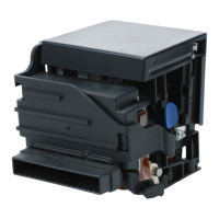
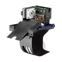
Please note that the Hengstler cable is supplied with a flying pigtail on the printer end.
This pigtail is intended to be fastened under the grounding screw, as shown in Fig. 2
and 3, to provide maximum reduction of radiated electrical noise.
For additional protection against accidental cable removal, the cable tie-downs (see
Fig. 2 and 3) are provided as a point to which you may fasten cables using cable ties
(not provided).
USB
The USB versions of the eXtendo
®
printer employ a standard digital camera USB
interface cable (5 pin Mini-B connector on the printer end) to communicate from the
host to the printer. Be sure that the Mini-B connector is fully engaged with the mating
connector on the printer. The other end of the cable plugs into the USB port on the
host.
Once the printer is connected with the host and the driver is installed, be sure to set
the Port in the driver to the appropriate USB port to match the physical host-side
interface cable port.
USB Pinout
Pin
Number Signal name I/O Function
1 NC no connection
2 D- I/O Data -
3 D+ I/O Data +
4 NC no connection
5 SGND I/O Signal Gnd
 Loading...