Installation MACH102
Release
06
09/2014
37
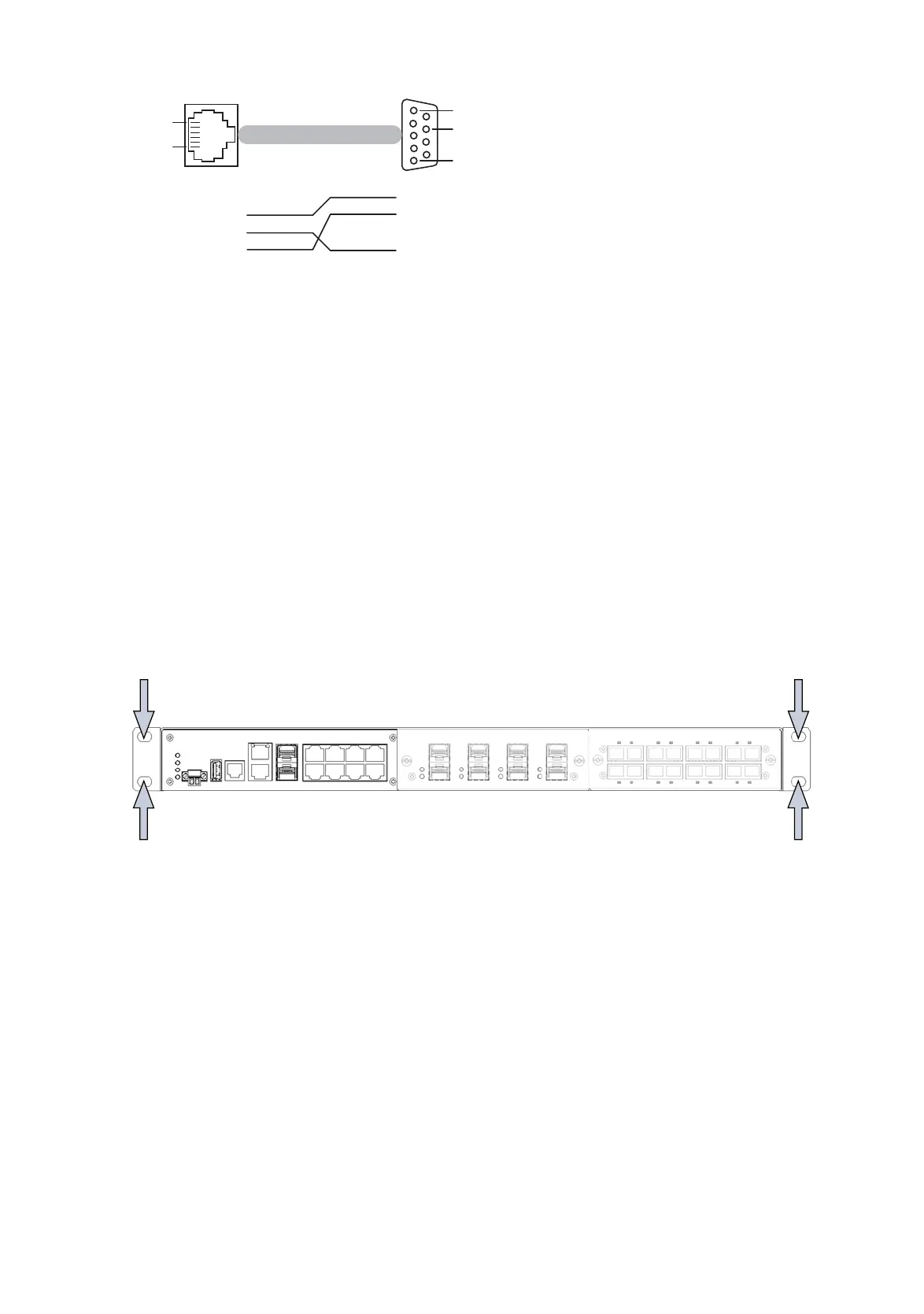
Figure 23: Pin assignment of the V24 interface
Note: You will find the order number for the terminal cable, which is
ordered separately, in the Technical Data chapter (see on page 39 “Tech-
nical data”).
2.4 Disassembly
Removing the device
To detach the device from the switch cabinet or the wall, remove the
screws from the brackets on the device.
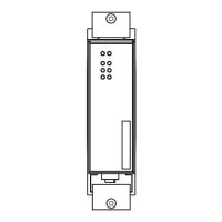
Figure 24: Disassembly
Pin 1
Pin 1
Pin 8
Pin 5
Pin 6
RJ11 DB9
2
3
5
1
2
3
4
5
6
CTS
n.c.
TX
GND
RX
RTS
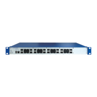
MACH 100
LS DA
USB
V.2 4
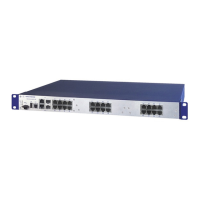
MACH 1000
2
1
LS DA
3
4
9
10
P
StandByRM
FAULT
R1
R2
5
6
7
8
13
14
11
12
17
18
15
16
21
22
19
20
25
26
23
24
LS DA
LS DA
LS DA
LS DA

 Loading...