Section 13 - Checkout
63-8594-02 Honeywell Economizers 168
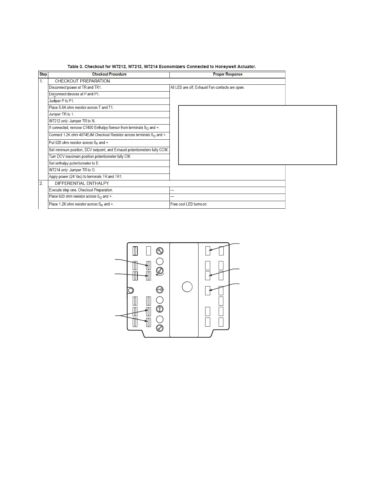
Standard Checkout Procedure
Checkout W7212
To checkout the operation of the W7212,
W7213 or W7214:
1. Remove the MAT or DAT sensor from
T-T1.
2. Remove the jumper from P-P1 and place
it on T-T1.
3. Remove the OAT and RAT sensors from
SO and SO+ and SR and SR+.
4. Place a 620 ohm resistor across SO and
SO+ and a 620 ohm resistor across SR
and SR+.
5. Connect the actuator to the + and -.
6. Provide 24 Vac to TR and TR1
7. Provide 24 Vac hot to terminal 1.
8. The motor will drive open.
9. Remove the 24 Vac from TR and TR1 and
the motor should drive close.
If using a Honeywell DCA, the + on the logic
module will be connected to 3 and does not
need to be connected to – since the actuators
are internally connected to ground.
When the first line of a procedure states:
“Execute step one. Checkout Preparation.”
this directs you to reset the logic module
to the initial checkout mode before
proceeding.
620 OHM 1/4W
RESISTOR
REMOVE
JUMPER P-P1
JUMPER T-T1
M23971A
N1
P1
T1
B
A
SR
SO
AQ
C
D
Free
Cool
EXH
IAQ
EXH
Set
IAQ
Max
IAQ
MIN
Min
Pos
Open
P
T
AQ1
SO+
SR+
N
EF1
5
2
24
VAC
COM
–
TR1
24
VAC
HOT
TR
4
EF
1
+
3
24 VAC POWER
0-10 VDC OUT
TO ACTUATOR
24 VAC POWER
(HOT) TO 1

 Loading...