Section 8 - W6215, W7215 And W7460 Economizer Modules
71 Honeywell Economizers 63-8594-02
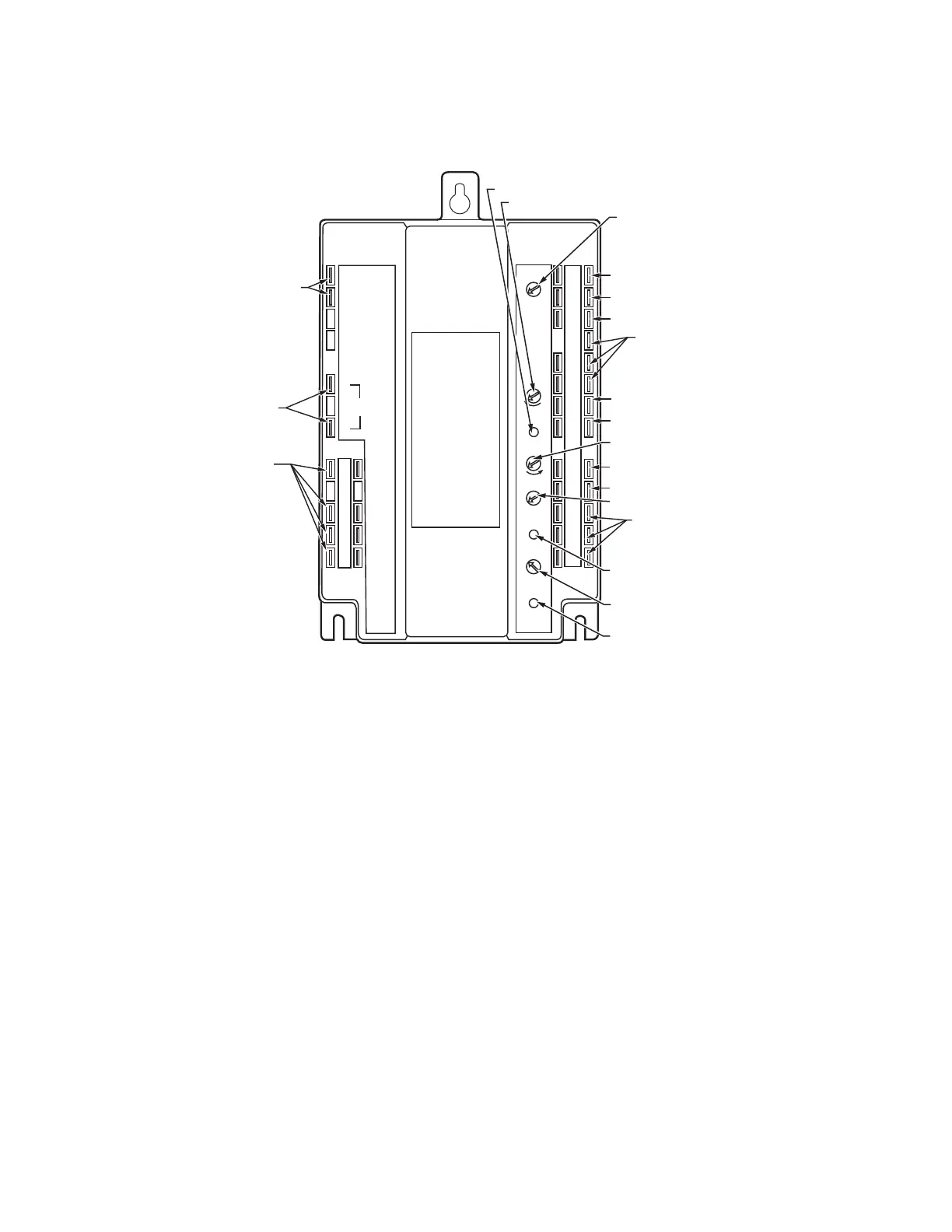
W6215, W7215 and W7460 Components
The W7215A is an economizer module for use
with series 72 actuators. The W7215B is
similar except for an outside air content sensor
input and slightly different contact inputs and
outputs. The W6215A was for use with series
62 actuators but otherwise identical to the
W7215A. The W7460A was for use with the
M7415 actuator.
W7215B and W7460B Components
The W7215B and W7460B are equipped with
outdoor air content sensor inputs. There are
slight variations to the input and output
terminals:
• The purge function is eliminated.
• An alarm contact output is added for when
the indoor DCV and outdoor air content
setpoints are simultaneously exceeded.
• The exhaust fan setpoint and exhaust
indication light are eliminated.
• An outdoor air content sensor setpoint and
indication light are added.
24VAC
TR Hot
24VAC
Com
24VAC
Hot
2-10V
OUT
Free
Cool
Unit
Control
Exhaust
Fan
Indoor
Fan
Mininum
Position
Maximum
Position
Open
Free Cool
Closed
ISI
Exhaust
Exhaust
Set Pt
0%
100%
50%
2V
6V
10V
ISI
Set Pt
A
BC
D
TR1
Com
+
+
5
2
4
1
T1
T
P1
Q1
AQ1
AQ
SD1
SD
AC1
AC
PG1
PG
So
Sr
W7215A
+
–
SINGLE ENTHALPY SETPOINT
MAXIMUM DAMPER POSITION
SETPOINT FOR DCV
DCV SENSOR SETPOINT
EXHAUST FAN ENERGIZED
SETPOINT
Q
M23898A
+
–
ACTUATOR POWER
SUPPLY TERMINALS
ACTUATOR
CONTROL
TERMINALS
CONTACT
OUTPUTS
NOTE: ALL INPUT AND OUTPUT WIRING MUST BE 24 VAC CLASS 2.
TRANSFORMER TERMINALS
OUTSIDE AIR ENTHALPY SENSOR
RETURN AIR ENTHALPY SENSOR
COOLING SWITCHING
CONTROLLED FROM
COOLING STAT TO COMPRESSOR
(TERMINALS 1-5)
MIXED AIR SENSOR
REMOTE MINIMUM POSITION
POTENTIOMETER
REMOTE MAXIMUM DAMPER POSITION
POTENTIOMETER
CONTACT INPUTS TO INITIATE
CONTROL SEQUENCES
Q
DCV MODE LIGHT
CO
2
SENSOR INPUT
EXHAUST FAN ENERGIZED LIGHT
MINIMUM DAMPER POSITION SETPOINT
P
FREE COOLING MODE LIGHT
3

 Loading...