Section 4 - H705 Economizer Module
63-8594-02 Honeywell Economizers 44
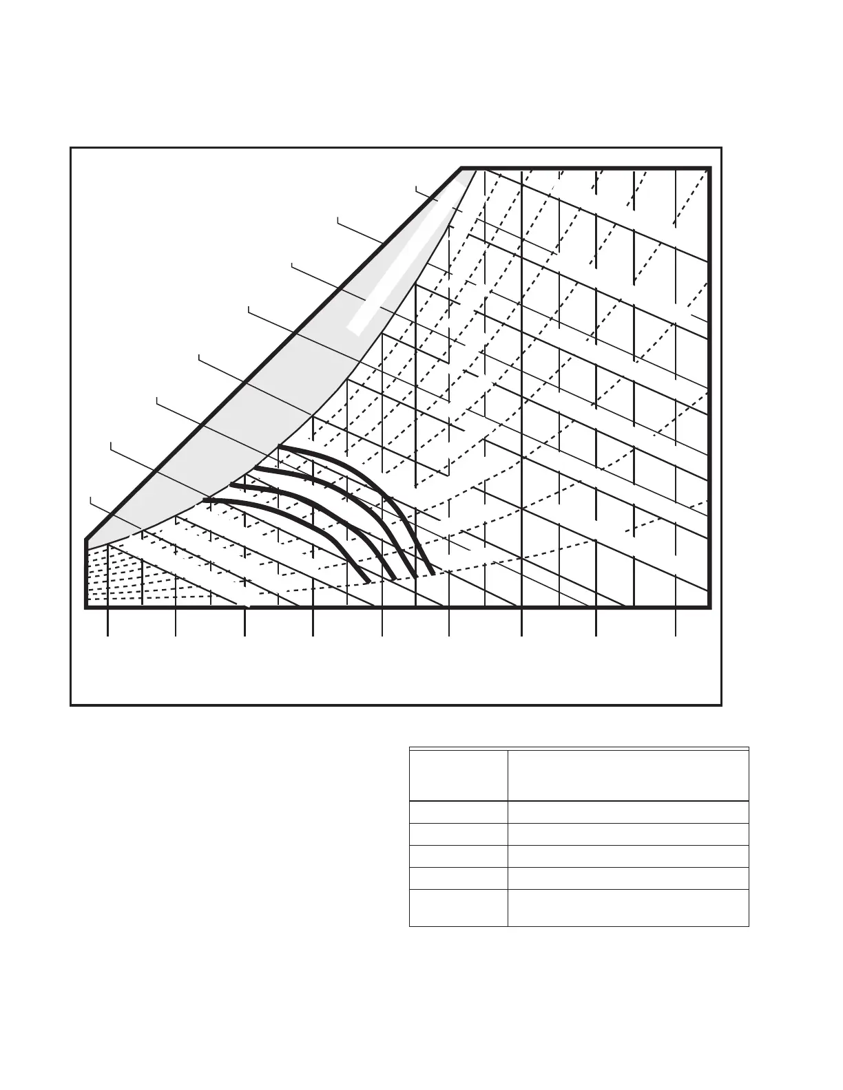
H705 Enthalpy Setpoint
This psychrometric chart shows effects of the
various analog economizer logic setpoints
listed. This only applied to single enthalpy
controllers not differential enthalpy. Air with
conditions to the left of the curve is brought in
from outdoors to be used for cooling. When
the outdoor air conditions are to the right of the
curve, the dampers will be set at minimum
position for ventilation and the mechanical
cooling energized. For differential enthalpy the
setpoint knob or potentiometer was turned to
the D setting and the lower of return or outside
air brought into the building.
Example: With A, B, C, D potentiometer logic
module set at “C”. Dry bulb temperature at
65°F (18.3°C) and Relative Humidity (RH) at
50% RH the logic module would free cool on
first call for cooling for commercial thermostat.
40 F
4 C
50 F
10 C
60 F
16 C
70 F
21 C
80 F
27 C
90 F
32 C
100 F
38 C
110 F
43 C
120 F
49 C
35 F
2 C
45 F
7 C
55 F
13 C
65 F
18 C
75 F
24 C
85 F
29 C
95 F
35 C
105 F
41 C
115 F
46 C
F 0 9
) C 2 3 (
B L U B T E W
F 5 8
) C 9 2 (
B L U B T E W
F 0 8
) C 7 2 (
B L U B T E W
F 5 7
) C 4 2 (
B L U B T E W
F 0 6
) C 6 1 (
B L U B T E W
F 5 5
) C 3 1 (
B L U B T E W
F 0 5
) C 0 1 (
B L U B T E W
5 4
F
(
7
) C
B L U B T E W
0 4
F
(
4
) C
B L U B T E W
5 3
F
(
2
) C
B L U B T E W
H R % 0 8
H R % 0 7
H R % 0 3
H R % 0 4
H R % 0 5
H R % 0 6
H R % 0 9
H R % 0 1
H R % 0 2
H R % 0 0 1 - N O I T A R U T A S
F 0 7
) C 1 2 (
B L U B T E W
F 5 6
) C 8 1 (
B L U B T E W
DRY BULB TEMPERATURES
15
BTU/LB
34.8 k-
J/kg
20 BTU/LB
46.4 k-J/kg
25 BTU/LB
58 k-J/kg
30 BTU/LB
69.7 k-J/kg
35 BTU/LB
81.4 k-J/kg
40 BTU/LB
92.8 k-J/kg
45 BTU/LB
104.5 k-J/kg
50 BTU/LB
116 k-J/kg
A
B
C
D
M25282
Control
Curve
Control Point
(Approximate Temperature
at 50% Humidity)
A 73°F (23°C)
B 70°F (21°C)
C 67°F (19°C)
D 63°F (17°C)
Knob turned
to D
For Differential Enthalpy (2 Sensor)

 Loading...