Section 9 - W7212, W7213 and W7214 Economizer Modules
63-8594-02 Honeywell Economizers 84
All other inputs are same as other logic
modules, for space consideration the enthalpy
sensor terminals were moved to left side of
control.
Same input for TR-TR1 for 24 Vac power to
logic module and output to mechanical
cooling.
Output for 2-10 Vdc and 24 Vac power to
actuator is on the right side of the unit and
power exhaust fan output.
The exhaust setpoint determines when the
exhaust fan runs based on damper position.
When the exhaust fan call is made, the
module provides a 60 ±30 second delay
before exhaust fan activation. This delay
allows the damper to reach the appropriate
position to avoid unnecessary fan overload.
EF and EF1 are 24V dry contacts only. An
external line voltage contactor is required to
operate the exhaust fan.
When the exhaust fan is deactivated the EF
and EF1 relay opens immediately.
The exhaust setpoint determines when the
exhaust fan runs based on damper position.
Full CCW is fully closed damper position and
Full CW is fully open damper position.
When the EF and EF1 contacts are made after
the 60 ±30 sec. delay, the EXH LED will
illuminate.
Damper minimum position and maximum
position are the positions of the damper for
ventilation for building contaminants and
people occupancy. See section 1 for
explanation of DCV and determination of
damper settings.
DCV Maximum Position
Adjustment
1. Disconnect mixed air sensor from
terminals T and T1 and short terminals T
and T1.
2. Connect a jumper between terminals AQ
and SO+.
3. Connect 24 Vac across terminals TR and
TR1.
4. Adjust the potentiometer on the face of
the device with a screwdriver for desired
maximum position.
5. If all minimum and maximum position
adjustments are complete, remove the
T-T1 jumper and reconnect the mixed air
sensor.
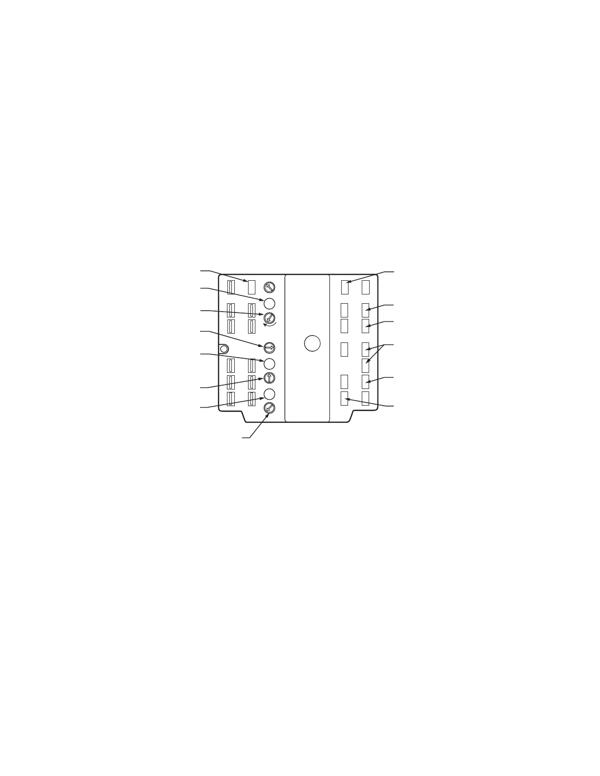
DCV SETPOINT
ENTHALPY
CHANGEOVER SETPOINT
LED LIGHTS WHEN
DCV INPUT IS
ABOVE SETPOINT
POWERED WHEN
OCCUPIED
LED LIGHTS WHEN
EXHAUST FAN CONTACTS
ARE CLOSED
MINIMUM DAMPER
POSITION SETTING
M23969B
N1
P1
T1
B
A
SR
SO
AQ
C
D
Free
Cool
EXH
IAQ
EXH
Set
IAQ
Max
IAQ
MIN
Min
Pos
Open
P
T
AQ1
SO+
SR+
MAXIMUM DCV
SETPOINT
LED LIGHTS WHEN
OUTDOOR AIR IS
SUITABLE FOR
FREE COOLING
N
EF1
5
2
24
VAC
COM
–
TR1
24
VAC
HOT
TR
4
EF
1
+
3
24 VAC INPUT
24 VAC TO
ACTUATOR
2-10 VDC TO
ACTUATOR
OUT TO COOL 1
OUT TO COOL 2
EXHAUST
FAN OUTPUT

 Loading...