Fire Alarm Control Panel IQ8Control C / M
FB 798951.10.GB0 / 04.15 41
BR2 Solder jumper to set whether the two batteries are connected and the monitoring for the free
battery connection should be switched off.
Open (default) Connection of two batteries >Battery 1+2<
closed Connection of a single battery only to connector >Battery 1<.
(The power charge and monitoring of >Battery 2< is disabled)
BR 3 / BR 4
Solder/jumper for wiring the LCD indicator panel via the RS 485 interface
BR7
Solder jumper for enabling an internal printer
D21
Integrated circuit, replacement not required
F1
Mains fuse T1.25A H / 230 V DC
F2
Fuse T2,5A battery charge current, battery 1
F3
Fuse T2,5A battery charge current, battery 2
F4
Fuse T2A 12 V DC power supply +Ub
ext
for external devices
V46
lights during emergency operation Limited functionality of the Panel
S2
DIL switch Operating mode "OFF" (factory default)
Service mode ”ON“ (software update via USB interface)
V62 / V63 LED V62 lits red Reversed polarity of the connected TTY cable
LED V63 lits green to check data communication if the TTY-interface is enabled
X1
Transformer connection (primary site)
X2
AC mains connector terminal L1/U, N, PE; for cable with 1,5 - 2,5 mm
2
X3 Connector for the micro module slot, the internal serial interface TTY / RS 485-1, the common
trouble relay, inputs I1 and I2, the control voltage for the built-in printer and the power supply
(12 V DC, Ub
ext
) for external equipment
The RS 485-2 interface connection is not supplied!
X7/X8 (LED V2)
Cover contact connection (FACP housing). LED V2 lights while the cover is open.
X9-A, 10-B
Connector for the power supply module (Part No. 802426 from Index G)
X11-A, 12-B
Micro module slot for a selectable micro module
X23 Connector for the built-in printer via a 26 pole ribbon cable
(For installation in
cabinet the ribbon cable Part No. 750756 max. 50 cm or 750757 max. 120 cm
is required)
X24
Connector for the operation panel via a 40 pole ribbon cable
X27, 28, 29, 30
Jumpers to configure the EMI protection for an essernet
®
micro module.
X31
Connector for the Service-PC (optional panel interface required)
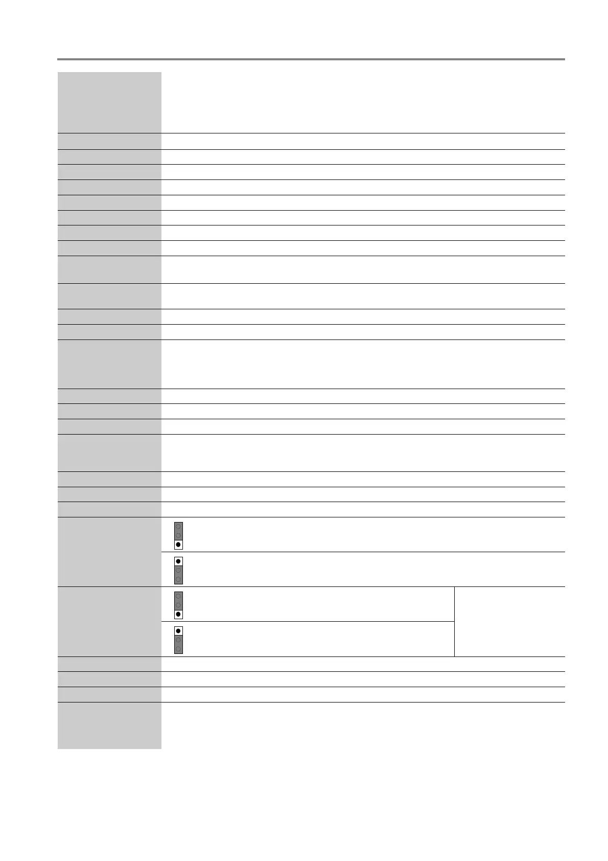
X32
1
2
3
Pos 1/2 RS485-1 terminating resistance activated
1
2
3
Pos 2/3 RS485-1 terminating resistance not activated
X34
1
2
3
Pos 1/2 RS485-2 End of line resistor activated
(do not alter factory default)
The RS485-2 interface is
not supplied for this
panel version.
1
2
3
Pos 2/3 RS485-2 terminating resistance not
activated
X33/35
Jumper for the RS 485-2 interface (do not alter position)
X45, X46
Jumper for factory settings only ( do not alter ISB)
USB
Connector for the service-PC and USB-Interface for a System software update.
Ethernet, Phone box,
HW FAILSAFE, USL,
ISB, Smart card
Internal devices and terminals for future system developments

 Loading...