Section 2: Mounting and Wiring
7
Wire the Communicator
UL
Installation must be in accordance with; the National Electrical Code.
The communicator must be connected to a UL Listed compatible control panel.
All interconnecting wires between the UL Listed control panel and the communicator must be less
than 20 feet in length contained in the same room. All interconnecting wiring must be installed in rigid
metal conduit or EMT (Electrical Metallic Tubing) where exposed on interior walls; or in flexible metal
tubing if run in the walls or ceiling.
All equipment used for the IP connection (such as the router, hub, modem, etc.) shall be listed, must
be powered from an un-switched branch circuit, and be provided with appropriate standby power.
A UL listed control panel must monitor the radio fault output of the communicator.
Most Honeywell control panels support ECP data communication. Check the Installation and
Setup Guide for the control panel you are using to see if it supports ECP communication.
The communicator’s ECP wiring will be in parallel with keypads and other peripheral devices such
as RF receiver, etc., of the control panel. Wire length/gauge limitations are the same for the
communicator as they are for keypads and other peripheral devices. To wire the communicator,
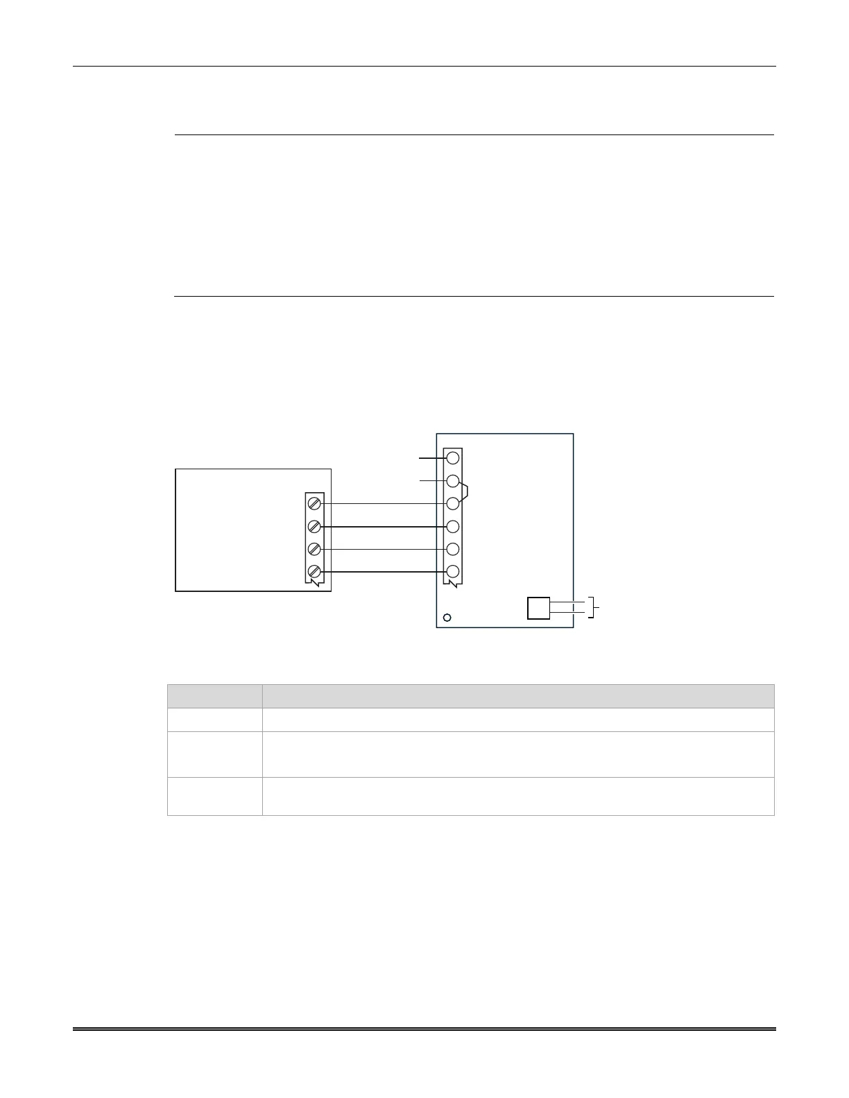
see the figure below and make the following connections:
COMMUNICATOR
CONTROL PANEL
IGSMCFP4G-013-V1
GND
ECP DATA OUT
ECP DATA IN
ECP (+) VOLTAGE INPUT
GND
DATA I N
BLK
YEL
GRN
RED
DATA OUT
+12 V AUX
2
6
1
4
5
3
TB1
NO CONNECTION
J1
AC INPUT 2
AC INPUT 1
NO CONNECTION
NO CONNECTION
Item Notes
Wiring
UL: Use minimum 18AWG wire.
Power The communicator is powered from the control panel.
Ensure a jumper is installed between TB1 pins 2 and 3.
ECP data The control panel treats the communicator as an ECP device, so ensure to program the
control panel with the communicator’s device address.
 Loading...