10 PSE Series Instruction Manual — P/N LS10227-000NF-E:B 3/29/2021
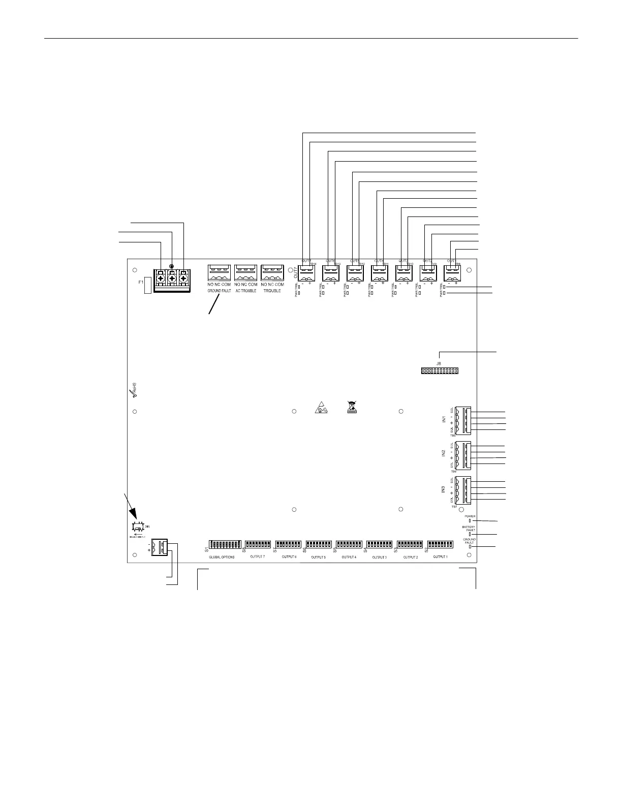
System Overview Switch SW1 - Ground Fault Detection
1.5 Switch SW1 - Ground Fault Detection
The Ground Fault Detection circuit monitors for ground faults. Switch SW1 is located on the lower left section of the power supply cir-
cuit board. Sliding SW1 to the left will disable ground fault detection by the power supply. This should only be done if ground faults are
being monitored by an FACP connected to the PSE power supply or in a cascading application as shown in Section 2.8 on page 18.
Figure 1.1 PSE-10 Board Layout
NAC/Out 7 -
NAC/Out 7 +
NAC/Out 6 -
NAC/Out 6 +
NAC/Out 5 -
NAC/Out 5 +
NAC/Out 4 -
NAC/Out 4 +
NAC/Out 3 -
NAC/Out 3 +
NAC/Out 2 -
NAC/Out 2 +
NAC/Out 1 -
NAC/Out 1 +
TB4 AC Power
Supervised,
Non-power-limited
AC2 (Neutral)
Earth
AC1 (Hot)
Form-C Relays
Non-supervised
SW1 Ground Fault
Detection
(slide left to disable)
(slide right to enable)
TB5, TB6, TB7
Command Inputs
Input #1
EOL
-
+
EOL
Input #2
EOL
-
+
EOL
Input #3
EOL
-
+
EOL
TB15 Supervised
+ Battery
- Battery
24 VDC
Non-power-limited
S2-S8
Programming DIP Switches
Activate output DIP switch changes by setting S1 positions 9 and 10
appropriately. Refer to page 24 for DIP Switch programming settings.
Each output circuit has its own dedicated programming DIP switch
J8
ZNAC-PS Connector
Power-limited (Class 2), Supervised, Special
Application or Regulated Outputs
LEDs
Power (green)
Batt/Chgr Fault (yellow)
Ground Fault (yellow)
Global
Options
Output 7 Output 6 Output 5 Output 4 Output 3 Output 2 Output 1
S1
Programming DIP Switch
for global options
Output Status LEDs
Trouble (yellow)
Power (red)
Note: The PSE-6 uses the same PCB
layout, however some terminals will be
depopulated, leaving the PSE-6 with five
output circuits and two inputs circuits.
AC Trouble and Trouble
relays are Fail-safe,
shown energized
(Optional relay for
Canadian applications)
 Loading...


