PSE Series Instruction Manual — P/N LS10227-000NF-E:B 3/29/2021 41
Controlling all Three Inputs with One Control Module Application Examples
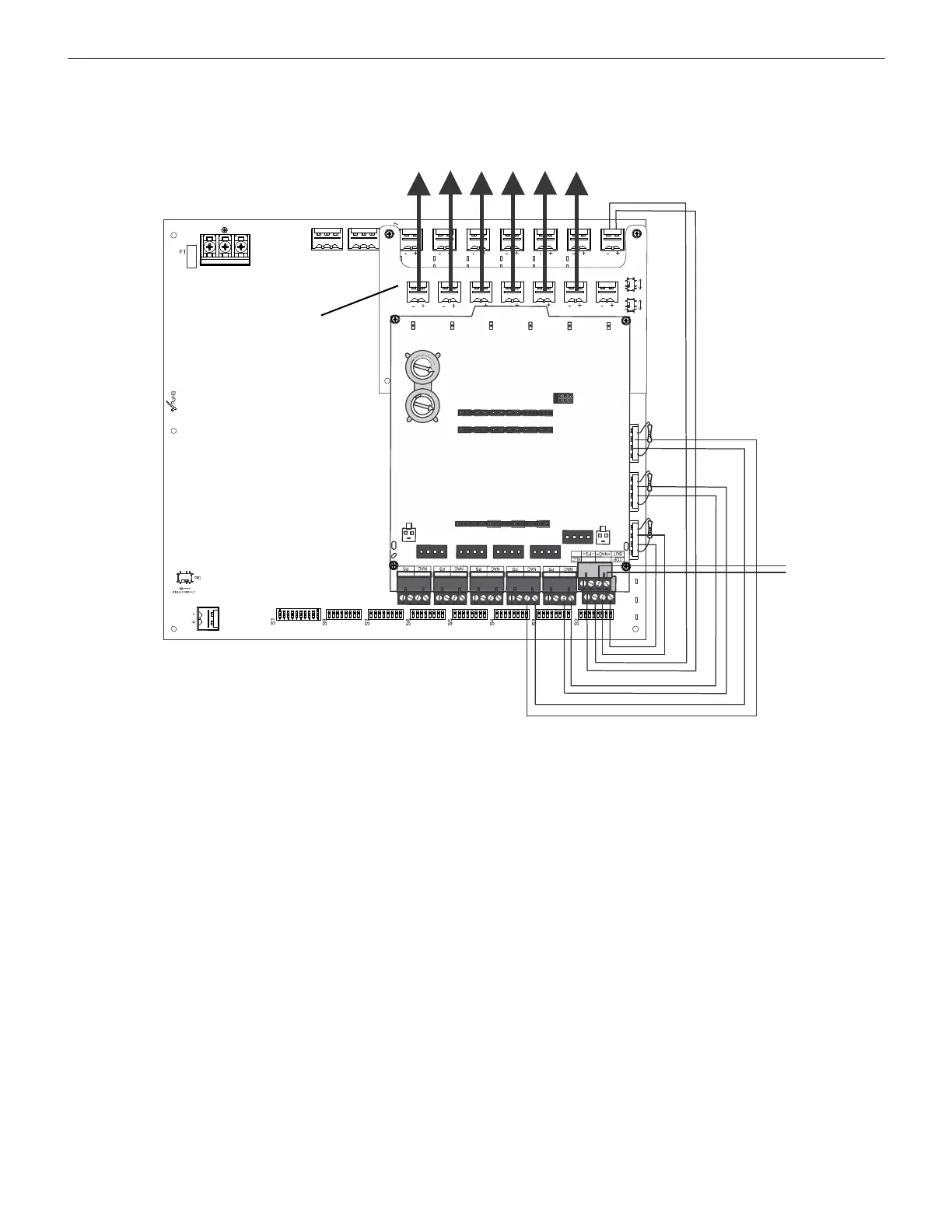
B.5 Controlling all Three Inputs with One Control Module
In this application, all three command inputs are being controlled by one multi-module, the XP6-C mounted inside the cabinet. Output
#1 is being used for 24 VDC aux power. Any output circuit may be configured to any input.
The following notes apply to Figure B.5.
• An End-of-Line Resistor must be installed between terminals 1 and 4 for control module wiring supervision (the ELR value is
dependent on the module/FACP employed).
• Either disable the unused addresses or install ELRs across unused outputs on the XP6-C.
• Refer to Section 3 for instructions on setting the DIP switches.
• Do not loop wires under screw terminals. Break wires to maintain proper supervision.
• For a list of compatible devices, refer to the Notifier Device Compatibility Document #15378.
• Refer to the SLC Wiring Manual for more information.
NO NC C NO NC C
TB4
TB15
T
B
2
T
B
1
T
B
1
3
O
U
–
+
–
+
–
+
–
+
–
+
–
+
–
+
–
+
–
+
–
+
–
+
T
1
0
J
1
B
A
S
E
A
D
D
R
E
S
S
+
0
B
A
S
E
A
D
D
R
E
S
S
+
1
B
A
S
E
A
D
D
R
E
S
S
+
2
B
A
S
E
A
D
D
R
E
S
S
+
3
B
A
S
E
A
D
D
R
E
S
S
+
4
B
A
S
E
A
D
D
R
E
S
S
+
5
S
W
1
T
1
+
1
+
0
+
2
+
3
+
4
+
5
T
0
T
2
T
3
T
4
T
5
T
1
1
T
1
2
T
1
3
T
1
4
T
1
5
T
1
6
0
1
2
3
4
5
6
7
8
9
1
0
1
1
1
3
1
4
1
5
1
2
0
1
2
3
4
5
6
7
8
9
NAC1
AUX1
NAC2
AUX2
24V Aux
Power
SLC
XP6-C
ZNAC-PS
Class A Converter
Option Module
Figure B.5 Controlling Three Inputs with One Module
 Loading...


