PW7K1R1E Wiring and Setup
Status LEDs
PW7K1R1E OSDP Reader Interface, Configuration, and Installation Guide, Document 800-26498 17
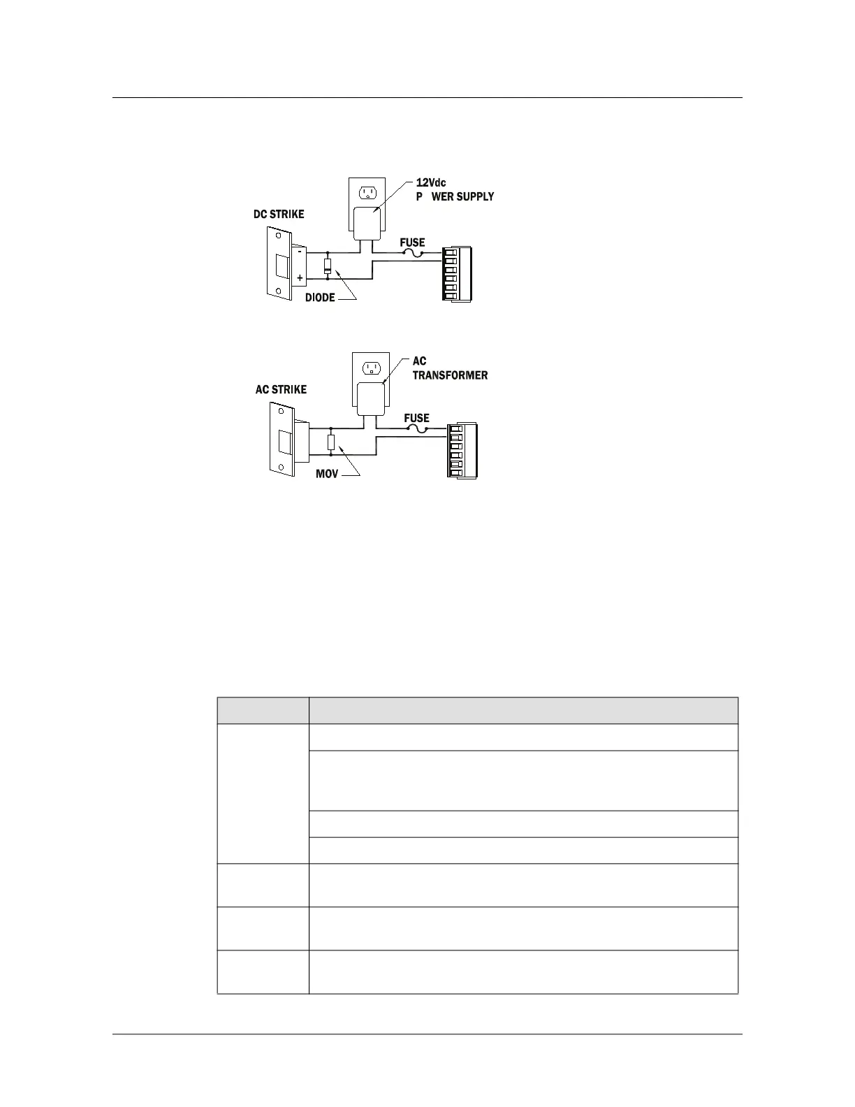
Figure 2-5: Relay Circuit Wiring Diagram
Note: The initial charge of the battery may take up to 24 hours to be fully charged.
2.13 Status LEDs
At power up, LED 1 turns ON then LEDs 2 through 7 are turned ON then OFF in
sequence.
Table 4: LED’s in Normal Running mode.
Diode Selection:
• Diode current rating: 1x
strike count
• Diode breakdown voltage:
4x strike voltage
• For 12VDC or 24VDC
strike, diode 1N4002
(100V/1A) typical
MOV Selection:
• Clamp voltage: 1.5x VAC
RMS
• For 24VAC strike,
Panasonic ERZ-
C07DK470 typical
LED DESCRIPTION
1
On-line, encryption disabled = 0.8 second ON, 0.2 second OFF
On-line, encryption enabled = 0.1 second ON, 0.1 second OFF, 0.1 second
ON, 0.1 second OFF0.1 second ON, 0.1 second OFF0.1 second ON, 0.3
second OFF
Off-line: 0.2 second ON, 0.8 second OFF
Waiting for application firmware to be downloaded:.1 sec ON,.1 sec OFF
2 Input IN1 Status: OFF = Inactive, ON = Active, Flashing = Fault. See note
2
3 Input IN2 Status: OFF = Inactive, ON = Active, Flashing = Fault. See note
2
4 Input IN3 Status: OFF = Inactive, ON = Active, Flashing = Fault. See note
2

 Loading...