18 www.honeywell.com
PW7K1R1E Wiring and Setup
IT Security
Note: : If this input is defined, every three seconds the LED is pulsed to its opposite
state for 0.1 second, otherwise, the LED is off
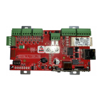
After the PW7K1R1E has received its IP address, the following table describes the
LEDs in the normal running mode. If the communication is lost, the PW7K1R1E
reverts back to the “waiting for IP address” mode:
2.14 IT Security
When installing the PW7K1R1E, it is important to ensure that it is done in a secure
manner.
Upon installation, the user accounts to the web configuration page should be created
with secure passwords, and that all DIP switches are in the off position for the normal
operating mode. The PW7K1R1E is shipped from the factory with a default login
account, which is enabled when DIP 1 is moved from OFF to ON. The default login
user name and password will be available for five minutes once enabled. Therefore, it
is important that at least one user account is defined, and the DIP switches are set to
OFF before the PW7K1R1E is commissioned. It is also highly recommended not to
configure the PW7K1R1E with an IP address that is accessible from the public
Internet
5 Input IN4 Status: OFF = Inactive, ON = Active, Flashing = Fault. See note
2
6 Input IN5 Status: OFF = Inactive, ON = Active, Flashing = Fault. See note
2
7 Input IN6 Status: OFF = Inactive, ON = Active, Flashing = Fault. See note
2
J1-YELLOW Ethernet speed: OFF = 10 Mb/S, ON = 100 Mb/S
J1-GREEN OFF = No Link, ON = Good Link, Flashing = Ethernet Activity
LED DESCRIPTION
1 On-line, encryption disabled = 0.8 second ON, 0.2 second OFF
On-line, encryption enabled = four pulses, 0.1 second ON, 0.1 second OFF per
second
2 Flashes when there is host communication
3 Flashes when data is received from either reader
4 Input IN1 Status: OFF = Inactive, ON = Active, Flashing = Trouble
5 Input IN2 Status: OFF = Inactive, ON = Active, Flashing = Trouble
6 Input IN3 Status: OFF = Inactive, ON = Active, Flashing = Trouble

 Loading...


