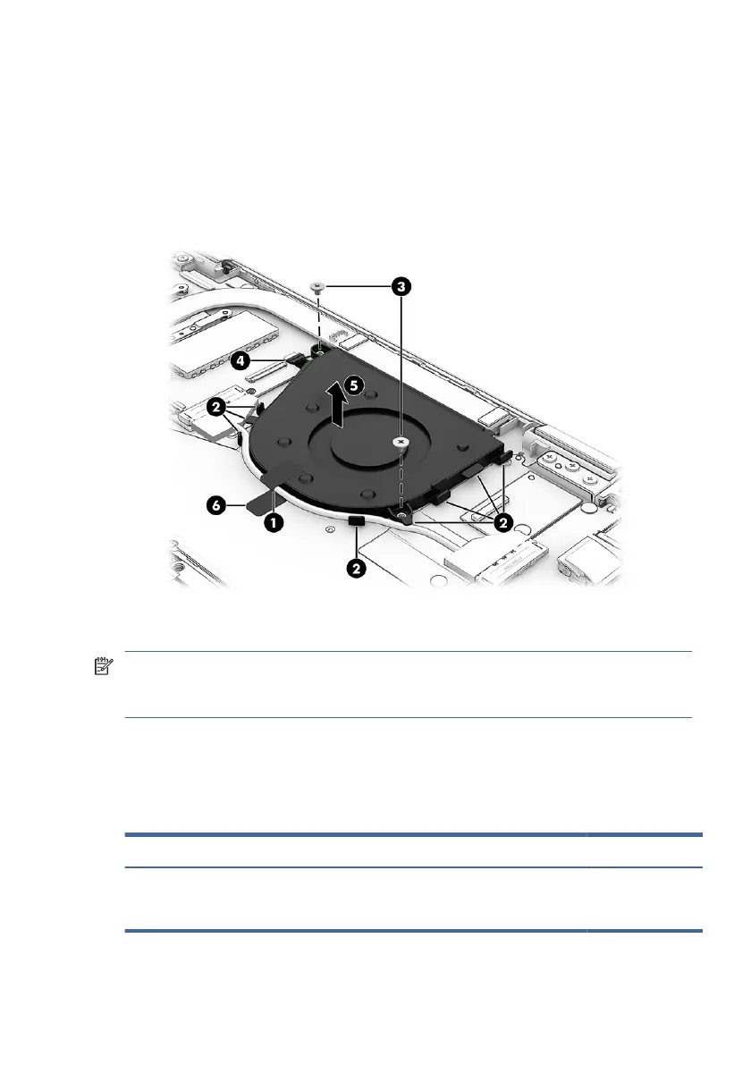
2. Remove the display cable and I/O board cable from the clips on the sides of the fan
(2).
3. Remove the two Phillips M2.0 × 2.5 screws (3) that secure the fan to the computer.
4. Disconnect the fan cable from the ZIF connector on the system board (4), and then
remove the fan (5). Note the tape under the fan (6) that also helps secure the fan to
the computer.
To install the fan, reverse this procedure.
NOTE: When replacing the tape (1) during fan installation, be sure the cables and tape
are as at as possible so they do not interfere with the bottom cover. Only place the
tape on the at fan surface.
Heat sink assembly
To remove the heat sink assembly, use this procedure and illustration.
Table 5-10
Heat sink description and part number
Description Spare part number
Heat sink assembly
NOTE: Thermal material is available as spare part number N15688-001.
N15687-001
Heat sink assembly 57
 Loading...