Model
2148
Installation
SECTION II
INSTALLATION
2-1
INTRODUCTION
2- 2
This
section provides
installation
instruct ions
fo
r the
instru
ment
and its accessories.
It
also includes in
fo
r
mat
ion
about
initia
l
inspection
and damage claims,
preparation
for
use
,
and packag i
ng,
s
tor
a
ge
and s
hipment.
2-3
INITIAL
INSPECTION
2- 4 I nspect the shipping
container
for
damage.
If
the con -
tainer
or
cus
hio
ning material
is
damaged, it should
be
kept
until
th
e
contents
of
the shipment have been checked
for
com
·
pleteness and the instr
ument
has
been checked
mechanically
and
electrically.
Th
e conte
nt
s
of
the shi
pment
s
hould
be
as
shown
in Figure
1-1
plus any accessories
that
were ordered
with
the i
nstrument.
Procedures
for
checking the electrical
operation
are given in Section 4.
If
the
contents
are
incomplete
,
if
there
is
mechanical damage or defect,
or
if
the in
strum
ent
does n
ot
pass
the operator's check
s,
notify
the nearest H
ewlett-
Packard
off
ice. Keep the shipping materials
for
car
'rier's insp
ec-
tion
.
The
HP
office
will
arrange
for
repair
or
replacement
with-
out
wa
iti
ng
for
settlement.
2-5
PREPARATION
FOR USE
2-6
Power Requirements
2-7
Th
e instrument requires a
power
source
of
100V,
120V
,
220V
or
240V
(+5%, - 10%) at a
frequency
of
48
to
66
Hz
single phase. The max
imum
power
·
consumption
is
380V
A.
2- 8 Line Voltage
Se
lect ion
CAUTION
BEFORE
SWIT
C
HING
ON
THIS
INSTRU
MEN
T make sure
that the
inst
rume
nt
is
set to the
local
line
voltage.
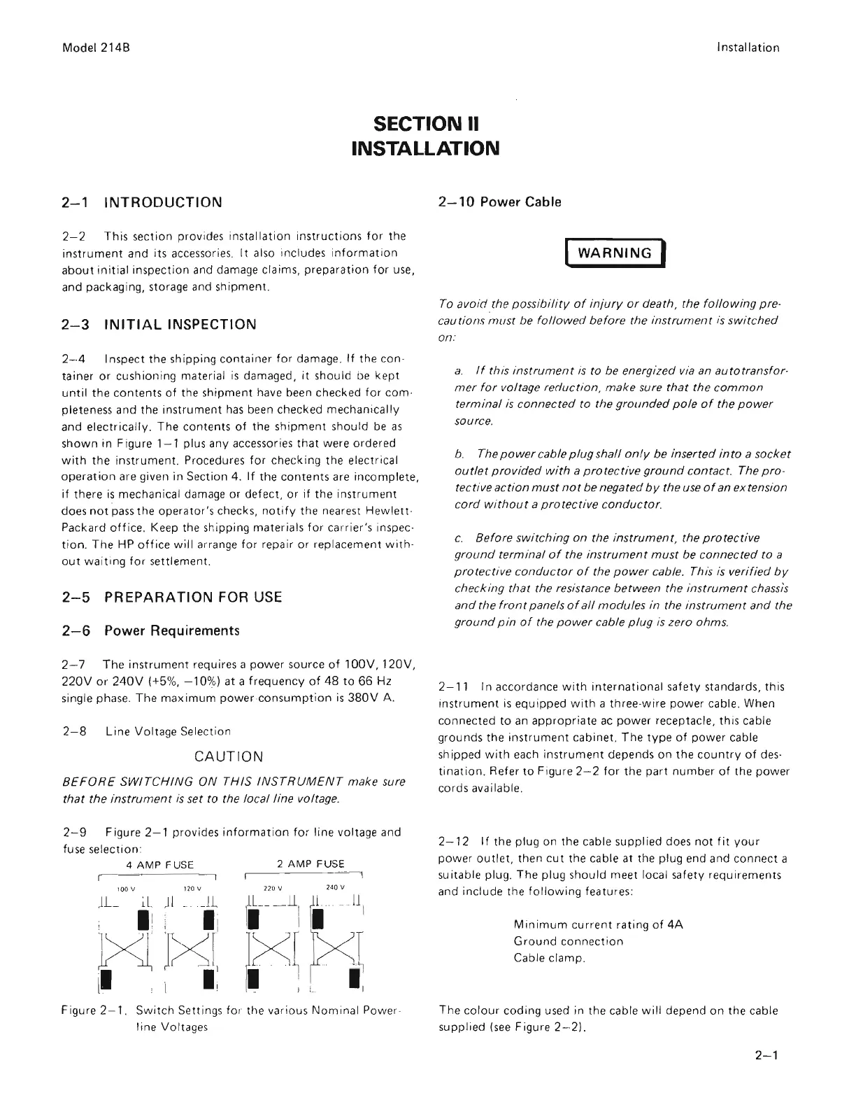
2- 9 Figure 2- 1 provides
information
for
line voltage and
fuse selection:
4AMPFUSE
2AM
PFUSE
100
V
1]0
v n
ov
240 V
Fi
gu
re 2- 1. S
witch
Settings for the various
Nominal
P
ower
-
line Voltages
--------
--
--_
.--
- - -
2-10
Power Cable
WARNING
I
To
avoid
the p
ossibility
of
injury
or
death, the
followi
ng pre-
cau
tion
s
mus
t be
followed
before
the
instrumen
t
is
switched
on:
a.
If
this
instrument
is
to be energized via an
autot
ra
nsfor-
me
r
for
v
olt
age
r
eduction
,
make
su
re
that
the
common
te
r
minal
is
c
onnected
to the
grounded
pol
e
of
the
power
source.
b. The
power
ca
ble
plug
s
hall
only
be
inserted
into
a
socket
outlet
provided
with
a p
rote
ctive
ground
contact.
The
pro-
tective ac
tion
must
not
be negated
by
the
use
of
an
extension
c
ord
without
a pr
otective
c
on
ducto
r.
c.
Before
switching
on
the ins
trument
, the
protective
ground
terminal
of
the
inst
ru
ment
must
be
connected
to
a
prote
ctive
conductor
of
the
power
cable.
Thi
s
is
ve
rif
ied
by
check Ing
that
the resistance between the Inst
rumen
t chassis
and
the
front
panel
s
of
all
modules
in the
instrument
and
the
ground
pin
of
the
power
cable
plug
is
ze
ro ohms.
2-
11
In
accordance
wi
th
international
sa
f
ety
st
andards, this
instrument
is
equipped
wi
th
a three-wire
power
cabl
e.
When
connected
to
an ap
pr
opria
te
ac
power
receptacle,
th
is
cable
grounds
the
instrument
cabinet. T he
type
of
power cable
sh ipped
with
each instr
um
e
nt
depends
on
the
country
of
des·
tination
. Refer
to
Figure 2- 2
for
the
part
number
of
the
power
cords available.
2- 12 I f
the
plug
on
the cab le suppl i
ed
does
not
fit
your
power
outlet,
then
cut
the cable at the plug end and connect a
suitable plug.
The
plug should meet local safety requirements
and include the
following
features:
Min
imum
current rating
of
4A
Ground
connection
Cable clamp.
The co lour
coding
used in
th
e cable
will
depend
on
the cable
supplied
(see
Figure 2- 2).
2-1
Scans by Artekmedia => 2009

 Loading...


