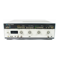
Model
214B
Operation
SECTION
III
OPERATION
3-1
INTRODUCTION
3-2
This
operating
section explains
the
functions
of
the
controls
and
indicators
of
the Model
214B
Pulse Generator.
Front
and rear panel
controls
and
connectors
are
identified
and
briefly
described in Figure
3-1.
A
more
detailed
des-
cription
of
the
control
and
connector
functions
is given in
the
following
paragraph
s.
3-3
SPECIAL OPERATING CONSIDERATIONS
3-4
Prior
to
operating the Model
214B,
the
operator
should
familiarise
himself
with
the
controls
and
connectors
by
reading
this
secti
on
in its entil·ety.
; .1 WARNING
17
When operating
in
the
30
-
100V
amplitude range, the
output
voltage
is
dangerous
to
life.
Care
should there-
fore
be
taken when connecting the
2148
to ex ternal
instruments.
3-5
The
following
steps should be
taken
before
applying
power
to
the
2148
.
a)
Read the safety summary at
the
front
of
this
manual.
b) Be sure the
power
selector switches are set
properly
for
the
power
source being used
to
avoid
instrument
damage.
Do
not
change the
LINE
SELECTOR
switch setting
with the instrument
on
or
with
power
connected
to
the
rear panel.
c)
When
connecting
the
2148
to
an
external
device,
ensure
that
the
device
cannot
be overloaded
by
the
2148
output
.
3-6
OPERATING MODE
3-7
The
2148
operating
mode
is
selected
by
pressing one
of
three
pushbuttons.
NORM
wh
en
rat
e is
det
erm ined by the
int
ernal
generator.
EXT
TRIG
when
an
external trigger source
is
connected.
GATE
when
the
int
ernal
re
petition
rate ge
nerator
need
s
to
be
swit
ched
on
only
fo
r
the
duration
of
an
external
gating signal.
3- 8 A
more
complete
descr
iption
of
the
se
th
r
ee
op
era
ti
ng
modes
is
given in the
following
paragraphs.
3-9
NORM MODE
3- 10
With
this
mode
sele
cted, the
frequency
is
se
t via
the
RATE
pus
hbutton
row
and the calibrated
RATE
vernier.
For
each
pushbutton
s
election
of
rate range, a correspond-
ing period range
is
shown
to
simplify
adjustm
e
nt
of
pulse
posit
i
on
and pulse
width,
i.e.
correct
timing
is ass
ur
ed when
the pulse pos
ition
and pulse
width
s
ettings
a
re
les
s
th
an the
selected
period
.
3-11
EXT
TRIGGER MODE
3-12
With
external trigger mode selected, a
2148
output
pulse
is
generated
either
by
applying
an external trigger
signal
to
the
EXT
INPUT
connector
or
by
operation
of
the
MAN
pushbutton.
3-13
When
operating
from
an external trigger source, the
trigger signal can be
from
dc
to
10MHz
,
with
minimum
amplitude
O.
5V
centred
on
the trigger level, and
minimum
pulse
width
1
Ons.
The
trigger slope
is
then selectable via the
SLOPE slide
switch,
and trigger level adjustable between
-5V
and
+5V
via the
EXT
INPUT
LEVEL
control.
NOTE
:
To
avoid incompatible timing settings, the pulse position
and pulse width settings should each
be
less than the
period
of
the external trigger signal.
3-14
When using
the
MAN
pushbutton
to
generate an
out
·
put
pulse,
the
SLOPE slide
switch
must be set
to
MAN,
and
then
a single pulse
is
generated every
time
the
MAN
push-
button
is
pressed.
Other
front
panel
controls
are set
to
obtain
the
desired pulse characteristics
e.g
. pulse
position,
pulse
width,
amplitude
.
3-1
Scans by Artekmedia => 2009

 Loading...