SVC 4-86
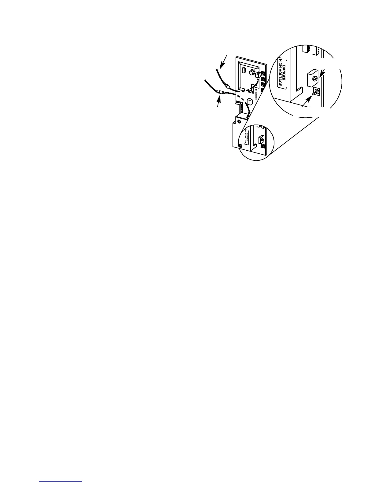
4. Connect a voltmeter between ground (TP1 on
the detector PCB or the aluminum oven top)
and the HV reference test point (TP7).
5. Set the voltage at an optimum point. This point
should be somewhere between -750 and
-850 V dc. Voltage setting should never ex-
ceed -950 V dc.
6. Perform a verification analysis.
Reset the voltage and perform another
analysis. Continue this sequence
until the maximum sensitivity is
attained (greatest area counts
for a given amount of sample
injected, divided by noise).
7. Install the right side panel and secure using four screws.
8. Install the electronics carrier top cover.
SIGNAL CABLE
HIGH
VOLTAGE
CABLE
HIGH VOLTAGE
REFERENCE
HIGH VOLTAGE
ADJUSTMENT
Artisan Scientific - Quality Instrumentation ... Guaranteed | (888) 88-SOURCE | www.artisan-scientific.com

 Loading...