SVC 3-19
Replace Electronic Flow Sensor Module
` HAZARDOUS VOLTAGES ARE PRESENT IN
THE INSTRUMENT WHEN THE POWER CORD
IS CONNECTED. AVOID A POTENTIALLY
DANGEROUS SHOCK HAZARD BY
DISCONNECTING THE POWER CORD
BEFORE WORKING ON THE INSTRUMENT.
` FLAME IONIZATION (FID) AND NITROGEN
PHOSPHOROUS (NPD) DETECTORS USE
HYDROGEN GAS AS FUEL. BE SURE ALL
HYDROGEN GAS IS TURNED OFF AT ITS
SOURCE BEFORE REPLACING ANY FLOW
COMPONENTS.
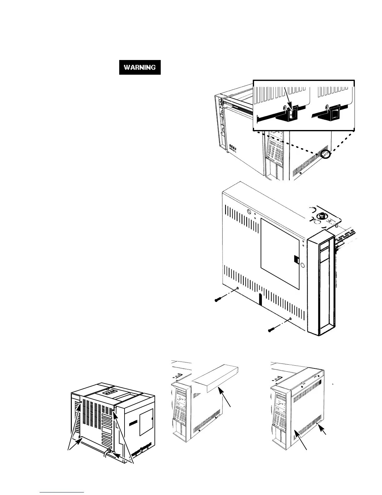
1. Set the main power line switch to the off position.
2. Disconnect the power cable from its receptacle.
3. Allow time for the oven and heated zones to cool.
4. When the heated zones are cool, turn off all gas
supplies.
5. Remove the two screws securing the left
side panel along its bottom edge.
6. Slide the left side panel towards the rear
of the instrument and lift.
7. Remove the four screws securing the rear
cover to the instrument.
8. Slide the rear cover towards the rear of the instru-
ment.
9. Remove the electronics carrier top cover
(above the signal cable plugs and receptacles
to expose the top edge of the
TCD detector PCB).
10. Remove the right side panel by
removing four screws: two each
along its top and bottom edges.
OFF ON
RED O VISIBLE
SCREWS
SCREWS
ELECTRONICS
CARRIER TOP
COVER
SCREWS
SCREWS
RIGHT SIDE PANEL
Artisan Scientific - Quality Instrumentation ... Guaranteed | (888) 88-SOURCE | www.artisan-scientific.com

 Loading...