SVC 7-1
Section 7
VALVES
This section is intended to help the technician isolate problems to a specific valve component or com-
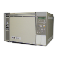
ponents. The HP 5890 Series II may be found in many different configurations, with varying component
options. This complicates the process of providing detailed troubleshooting procedures for even gener-
al problems. But, by using the general troubleshooting techniques presented here, successful results
should be achieved.
Specific part numbers are not given in this portion of the service manual. For all replacement part num-
bers, refer to the Section 7 of the IPB portion of this document.
This document is not meant to provide instruction for first time installation of any of the options dis-
cussed. The add-on sheets, which accompany the various options, exist for just this purpose, and
should be referenced when performing a first time installation.
TABLE OF CONTENTS
VALVES SVC 7-1. . . . . . . . . . . . . . . . . . . . . . . . . . . . . . . . . . . . . . . . . . . .
INTRODUCTION SVC 7-2. . . . . . . . . . . . . . .. .. . . . . . . .. . . . . . . . . . . . . . . . . . . . . . .
VALCO VALVES 18900F SVC 7-2. . . . . . . . . . . . . . .. .. . . . . . . .. . . . . . . . . . . . . . . .
General Purpose Valves (GPVs) SVC 7-4. . . . . . . . . . . . . . .. .. . . . . . . .. . . . . . . . . .
Adjustable Restrictors SVC 7-5. . . . . . . . . . . . . . .. .. . . . . . . .. . . . . . . . . . . . . . . . . .
Gas Sample Loops SVC 7-5. . . . . . . . . . . . . . .. .. . . . . . . .. . . . . . . . . . . . . . . . . . . . .
LIQUID SAMPLE VALVES (LSVs) SVC 7-6. . . . . . . . . . . . . . . . . . . . . . .. .. . . . . . . ..
Troubleshooting and Maintenance SVC 7-7. . . . . . . . . . . . . . .. .. . . . . . . .. . . . . . .
Chromatographic Symptoms SVC 7-7. . . . . . . . . . . . . . .. .. . . . . . . .. . . . . . . . . . . .
Loss of Sensitivity or Excessive Drift SVC 7-7.. . . .. . . . . . . . . . . . . . . . . . . . . . . .. .
Loss of Peaks in Specific Areas of the Chromatogram SVC 7-7. . . . . . . . . . . . . . ..
Baseline Upsets SVC 7-7. . . . . . . . . . . . . . .. .. . . . . . . .. . . . . . . . . . . . . . . . . . . . . . .
Extraneous Peaks SVC 7-8. . . . . . . . . . . . . . .. .. . . . . . . .. . . . . . . . . . . . . . . . . . . . . .
Locating Leaks SVC 7-8. . . . . . . . . . . . . . .. .. . . . . . . .. . . . . . . . . . . . . . . . . . . . . . . .
Pressure Check SVC 7-8. . . . . . . . . . . . . . .. .. . . . . . . .. . . . . . . . . . . . . . . . . . . . . . .
Valve Box Assembly Removal SVC 7-15. . . . . . .. . . . . . . .. .. . . . . . . .. .. . . . . . . ..
Valve Actuator Alignment SVC 7-16.. . . .. . . . . . . .. .. . . . . . . .. .. . . . . . . .. .. . . . .
Valve Actuation of GC-Controlled Valves SVC 7-17. . .. .. . . . . . . .. .. . . . . . . .. ..
Valve Configuration Diagrams SVC 7-18.. . . . . . . . . . . . . . . .. .. . . . . . . .. .. . . . . . .
Artisan Scientific - Quality Instrumentation ... Guaranteed | (888) 88-SOURCE | www.artisan-scientific.com

 Loading...