EasyManua.ls Logo

HP 5890 Series II User Manual

HP 5890 Series II
326 pages
To Next Page IconTo Next Page
To Previous Page IconTo Previous Page
Page #82 background image
SVC 4-12
Remove/Replace FID Diode Bridge Assembly
HAZARDOUS VOLTAGES ARE PRESENT IN THE INSTRUMENT WHEN THE POWER
CORD IS CONNECTED. AVOID A POTENTIALLY DANGEROUS SHOCK HAZARD BY
DISCONNECTING THE POWER CORD BEFORE WORKING ON THE INSTRUMENT.
1. Set the main power line switch to the off position.
2. Disconnect the power cable from its receptacle.
3. Lift the hinged top cover at its front edge,
exposing the detector area.
4. If an autosampler is installed on the instrument,
it will be necessary to remove it and its mount-
ing bracket to allow removal of the left side cov-
er as follows:
a. Remove the autosampler tray from its
mounting bracket by first simultaneous-
ly lifting and turning the two tray locks
which hold it in position, then sliding
the tray away from the instrument.
b. Lift the autosampler tray from its mount-
ing bracket and set it aside.
c. Remove the autosampler bracket by
removing the 6 screws securing it to
the instrument.
5. Remove the two screws securing the left
side panel along its bottom edge.
6. Slide the left side panel towards the rear
of the instrument and lift.
7. Remove the four screws securing the rear
cover to the instrument.
8. Slide the rear cover towards the rear of the
instrument.
OFF ON
RED O VISIBLE
SCREWS
SCREWS
Artisan Scientific - Quality Instrumentation ... Guaranteed | (888) 88-SOURCE | www.artisan-scientific.com

Table of Contents

Question and Answer IconNeed help?

Do you have a question about the HP 5890 Series II and is the answer not in the manual?

HP 5890 Series II Specifications

General IconGeneral
TypeGas Chromatograph
Oven Temperature RangeAmbient + 4°C to 450°C
Data System CompatibilityHP ChemStation
Injection Ports2
DetectorsUp to 2
Detector OptionsFID, TCD, ECD, NPD
Inlet OptionsSplit/Splitless, Cool on-column
Temperature ControlElectronic
Data OutputAnalog, Digital
Power Requirements50/60 Hz
Carrier GasHelium, Nitrogen, Hydrogen

Summary

Section 1 INTRODUCTION

HP 5890 Series II Gas Chromatograph Overview

General description of the instrument and its configurations for troubleshooting.

Electronic Troubleshooting Guide

Steps and strategies for diagnosing instrument issues based on symptom types.

Section 2 INLET COMPONENTS

Replacing Inlet Components

Procedures for removing and replacing various inlet components on the instrument.

Section 3 FLOW/PRESSURE CONTROL COMPONENTS

Flow/Pressure Control Components Overview

Description of components like regulators, mass flow controllers, and sensors.

Section 4 DETECTORS

Replacing Detector Components

Procedures for replacing components within different types of detectors.

Section 5 OVEN TEMPERATURE

Replacing Oven Temperature Control Components

Instructions for replacing components related to oven temperature control.

Section 6 ZONE TEMPERATURE

Replacing Temperature Control Components

Procedures for replacing components controlling temperature in various instrument zones.

Section 7 VALVES

Valves Introduction and Types

Information on VALCO valves, GPVs, LSVs, and their operational considerations.

Section 8 KEYBOARD AND DISPLAY

Keyboard and Display Replacement

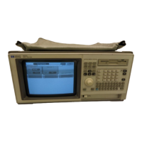
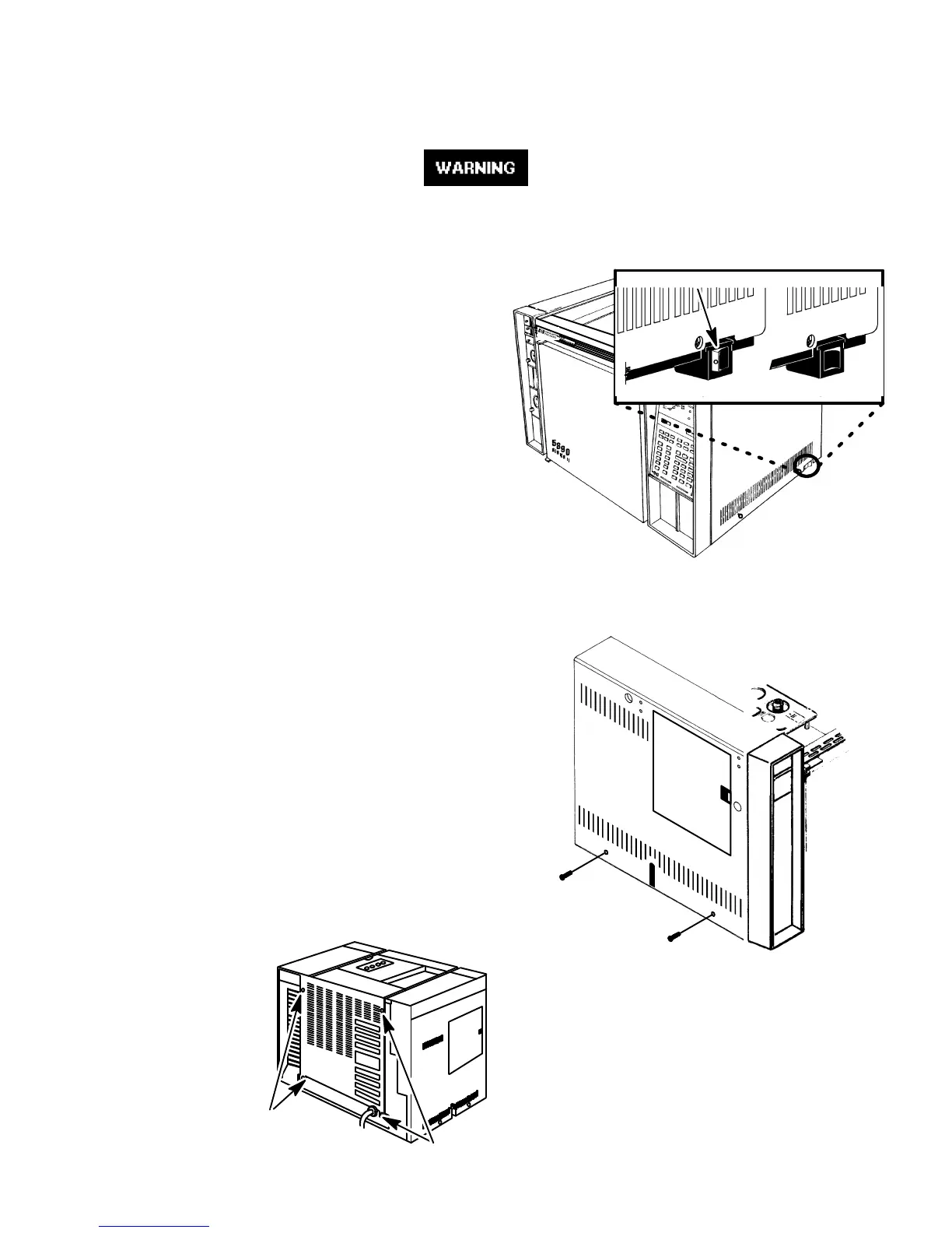
Procedures for replacing the keyboard and display assembly.

Section 9 MAIN PCB

Main PCB Components and Replacement

Information on the main PCB and its replacement procedure.

Section 10 DATA COMMUNICATIONS

Communication Interface Components

Overview of available data communication options and interface PCBs.

Section 11 POWER SUPPLY

Replacing Power Supply Components

Procedures for replacing power supply components like PCB, transformer, switch, cable.

Appendix A PCB CONNECTOR INFORMATION

Main PCB Connectors

Detailed pinout information for connectors on the main PCB.

Detector PCBs

Pinout details for detector PCBs.

EPC PCB Connectors

Pinout details for EPC PCB connectors.

Related product manuals