SVC 2-21
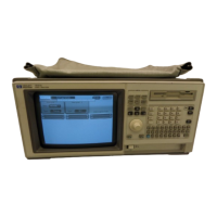
5. Remove the electronicscarrier top cover .
6. Remove the right side panel by
removing four screws: two each
along its top and bottom edges.
7. Remove the back cover of the
instrument by removing four
screwsand sliding the cover
off of the rear of the instrument.
8. Remove the PCOC fan cover by
removing the two screws securing it to the in-
strument. (Removal of the fan cover frees the
fan.)
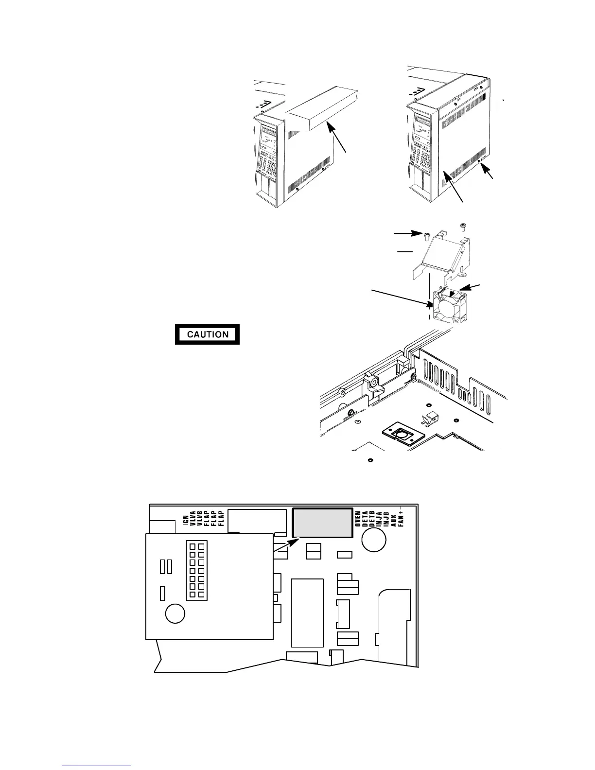
9. Trace the fan power wires to there destination
at connector P7 on the main PCB (exposed
right side of instrument).
WHEN DISCONNECTING A PLUG, PULL ON
THE PLUG NOT ON ITS WIRES. PULLING ON
THE WIRES MAY CAUSE BREAKAGE.
10. Disconnectconnector P7 from its receptacle by
pulling it straight off. (Heated zones corre-
sponding to sensor lead locations are labeled
to the right of the P7 connector receptacle on
the main PCB.)
Q6
C9
P7
Q3
C10
1
3
5
7
9
11
13
2 OVEN
4 DETA
6 DETB
8 INJA
10 INJB
12 AUX
14 FAN+
-
P 7
ELECTRONICS
CARRIER TOP
COVER
SCREWS
SCREWS
RIGHT SIDE PANEL
COOLING
FAN
FAN
SHROUD
FLOW
DIRECTION
ARROW
SCREW
Artisan Scientific - Quality Instrumentation ... Guaranteed | (888) 88-SOURCE | www.artisan-scientific.com

 Loading...