2-32
Installing the Switch
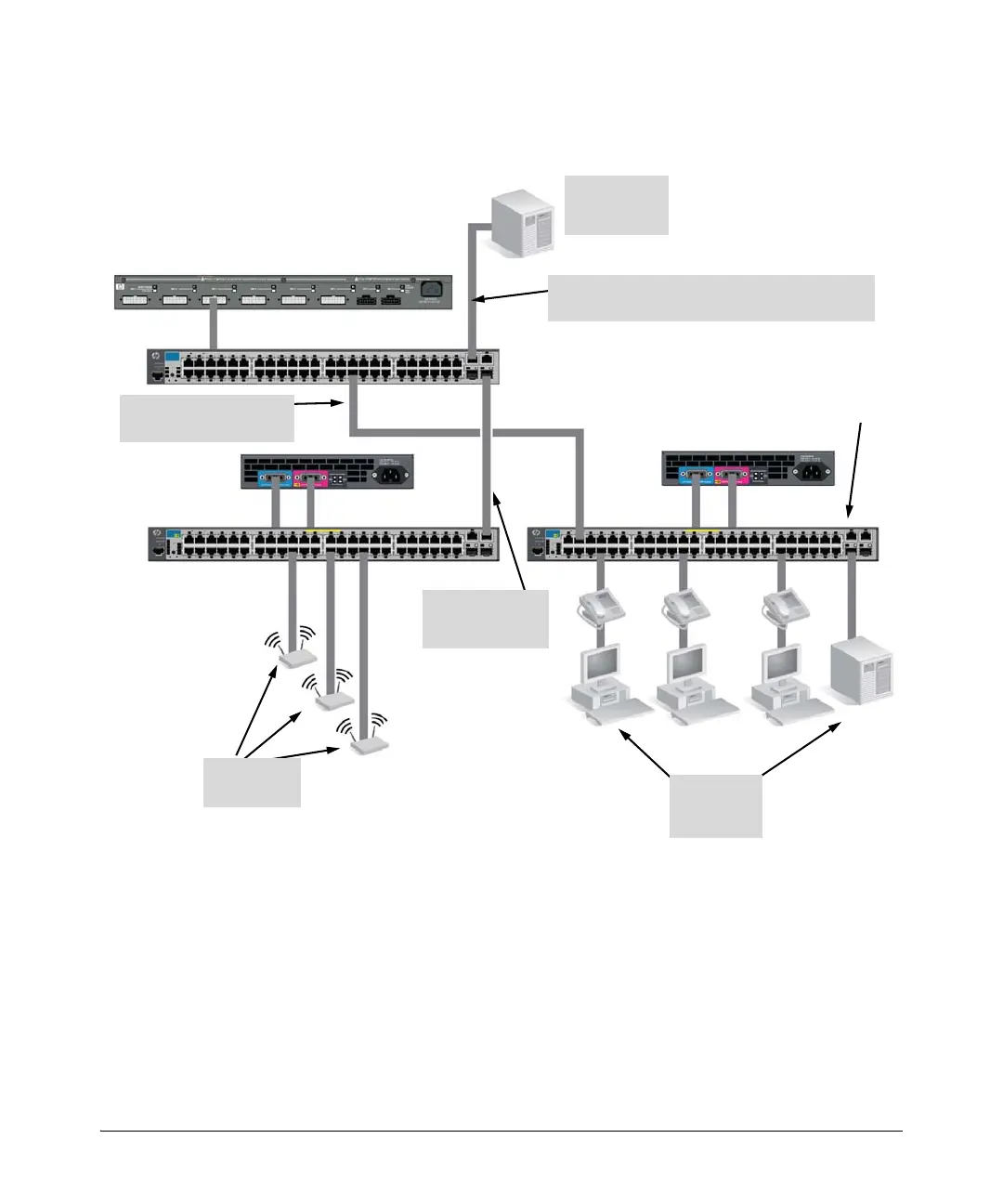
Sample Network Topologies for PoE+ Switches
As a Segment Switch Implementing PoE
Figure 2-24. Segment network configuration with PoE+ switches
As shown in the illustration above, the IP telephones have been inserted in
between the E2620-48-PoE+ Switch and the PCs, and wireless access points
(WAPs) have been connected to another E2620-48-PoE+ Switch. Both the
telephones and WAPs will receive PoE+ power from each of the switches.
Only devices directly connected to the PoE+ switches can receive PoE+
power. Devices connected to a non-PoE+ segment switch cannot receive
PoE+ power.
Server with
Gigabit
Ethernet NIC
E2620-48 Non-PoE+ Switch
E2620-48-PoE+ Switch
630 RPS/EPS
PCs, printers,
and local
servers
Twisted-pair straight-
through or crossover cables
Wireless
Access Points
Category 5e twisted-pair straight-through or
crossover cable for 1000 Mbps connection to server
Gigabit
fiber-optic cable
uplink
620 RPS/EPS
E2620-48-PoE+
Switch
 Loading...