4. Remove the system board (System board on page 39).
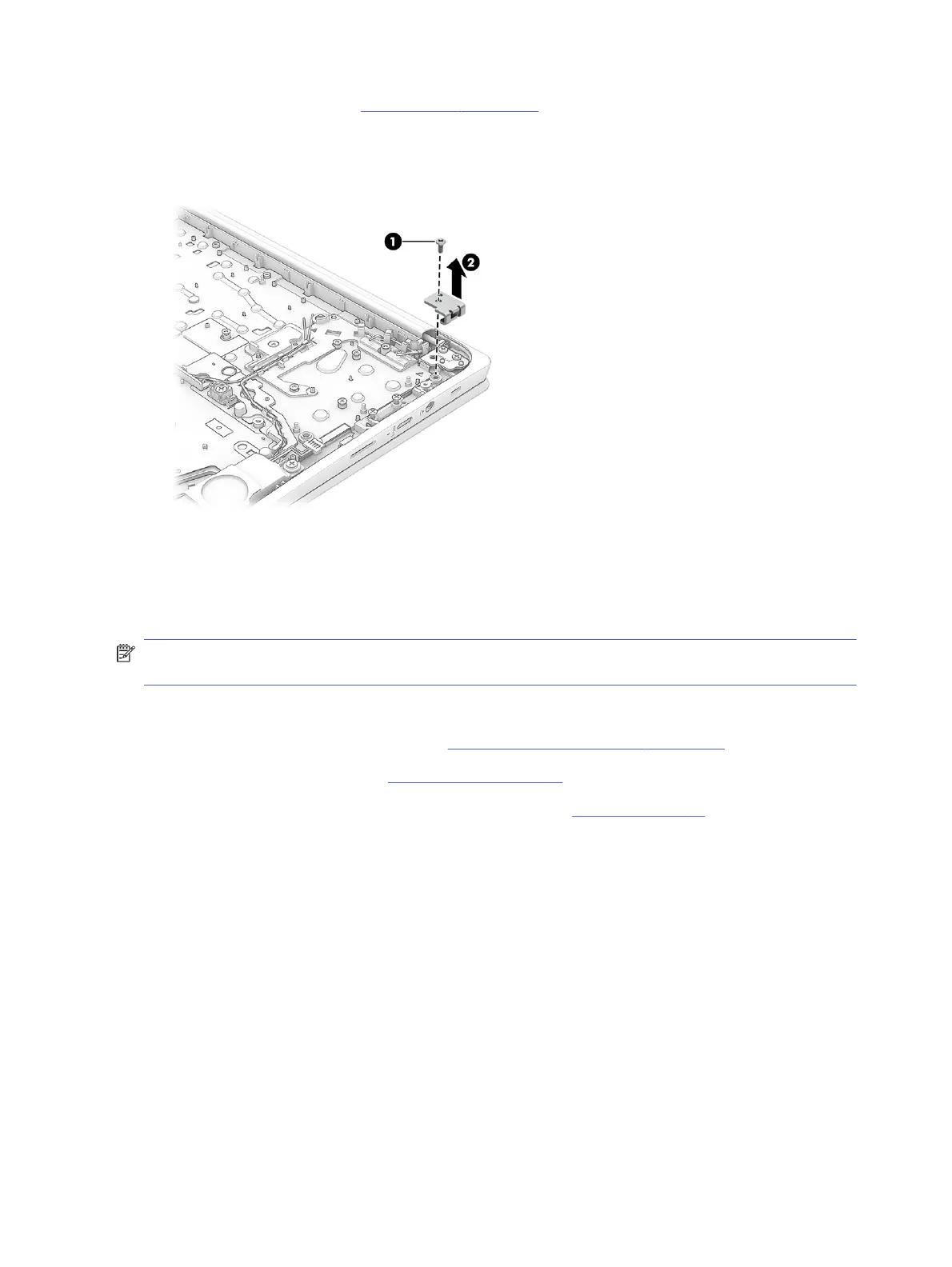
Remove the lock bracket:
■
Remove the Phillips M2.0 × 3.0 screw (1), and then remove the lock bracket (2).
To install the lock bracket, reverse this procedure.
Display assembly
To remove and disassemble the display assembly, use these procedures and illustrations.
NOTE: The display assembly is spared at the subcomponent level. For display assembly spare part
information, see the individual removal subsections.
Before removing the display panel, follow these steps:
1. Prepare the computer for disassembly (Preparation for disassembly on page 28).
2. Remove the bottom cover (see Bottom cover on page 28).
3. Disconnect the battery cable from the system board (see Battery on page 29).
Remove the display assembly:
44
Chapter 5 Removal and replacement procedures for authorized service provider parts
 Loading...