44
Appendix A Chassis views and technical
specifications
Chassis views
HPE 5930-32 QSFP+/HPE 5930-32 QSFP+ TAA
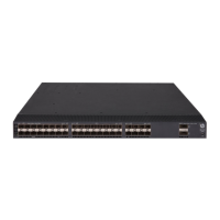
Figure 50 Front panel
(1) QSFP+ port (2) QSFP+ port LED
(3) System status LED (SYS)
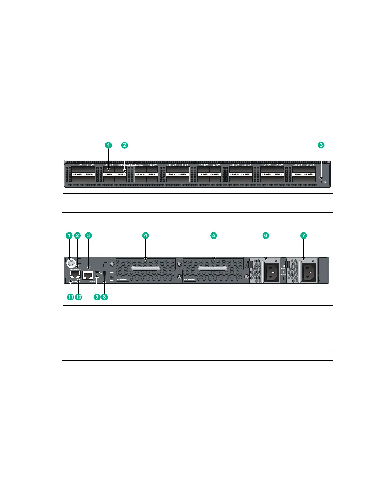
Figure 51 Rear panel
(1) Grounding screw (auxiliary grounding point 2) (2) Management Ethernet port
(3) Serial console port (4) Fan tray slot 1
(5) Fan tray slot 2 (6) Power supply slot 1
(7) Power supply slot 2 (8) USB port
(9) USB mini console port (10) LINK LED for the management Ethernet port
(11) ACT LED for the management Ethernet port
The HPE 5930-32 QSFP+/HPE 5930-32 QSFP+ TAA switch comes with the two power supply slots
empty and a filler panel as an accessory. You can install one or two power supplies for the switch as
needed. In Figure 51, two 650
W AC power supplies are installed in the power supply slots. For more
information about installing and removing power supplies, see "Installing/removing a power supply."
The HPE 5
930-32 QSFP+/HPE 5930-32 QSFP+ TAA switch comes with the two fan tray slots empty.
You must install two fan trays of the same model for the switch. In Figure 51, two LSWM1HF
ANSC
fan trays are installed in the fan tray slots. For more information about installing and removing fan
trays, see "Installing/removing a fan tray."
 Loading...