7
Installing the Switch
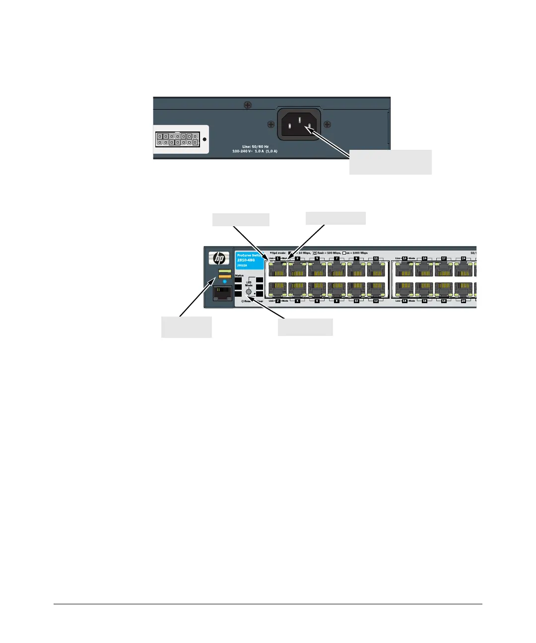
1.) Connect the power cord supplied with the switch to the power connector
on the back of the switch, and then into a properly grounded electrical
outlet.
2.) Check the LEDs on the switch as described below.
When the switch is powered on, it performs its diagnostic self test. Self
test takes approximately 50 seconds to complete.
Self Test LED Behavior:
During the self test:
• Initially, all the status, LED Mode and port LEDs are on for most of
the duration of the test.
• Most of the LEDs go off and then may come on again during phases
of the self test. For the duration of the self test, the Test LED stays on.
When the self test completes successfully:
•The Power and Fan Status LEDs remain on.
•The Fault and Test LEDs go off.
• The port LEDs on the front of the switch go into their normal opera-
tional mode:
– If the ports are connected to active network devices the Link
LEDs should be on.
– In the default LED Mode (Act), link activity is displayed on the
Port Mode LED.
ve 12 V System Power (RPS) Input
Connect power cord to
the power connector
Fault
Power
Locator
Console
RPS
Fan
Spd
FDx
Act
Test
Switch 2810-48G
Test LED
Power and
Fault LEDs
Port Mode LED
Port Link LED
 Loading...