1-6
Introducing the Switch
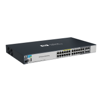
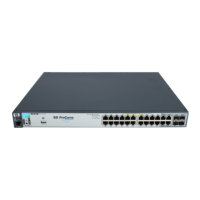
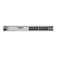
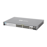
Front of the Switch
Introducing the Switch
Network Ports
■ 24 or 48 auto-sensing 10/100/1000Base-T ports.
All these ports have the “Auto MDIX” feature, which means you can use
either straight-through or crossover twisted-pair cables to connect any
network devices to the switch.
■ On the 2910al devices there are four dual-personality ports. Use either the
10/100/1000Base-T RJ-45 connector, or install a supported ProCurve mini-
GBIC (SFP) for fiber-optic connections.
The RJ-45 connectors support the “Auto MDIX” feature, which means you
can use either straight-through or crossover twisted-pair cables to
connect any network device to the switch.
Dual-Personality Port Operation. By default, the RJ-45 connectors are
enabled. If a mini-GBIC is installed in a slot, it is enabled and the associ-
ated RJ-45 connector is disabled and cannot be used. If the mini-GBIC is
removed, the associated RJ-45 port is automatically re-enabled.
The RJ-45 connector also supplies PoE+ power until a mini-GBIC is
installed. The PoE+ power is turned off when a mini-GBIC is plugged in.
■ Two expansion slots. These switches provide two slots in the back of the
device that can accept any of the al modules. The module provides port
connectivity for 10 gigabit speed. The module ports provide connectivity
through either copper or fiber optic media.
LEDs
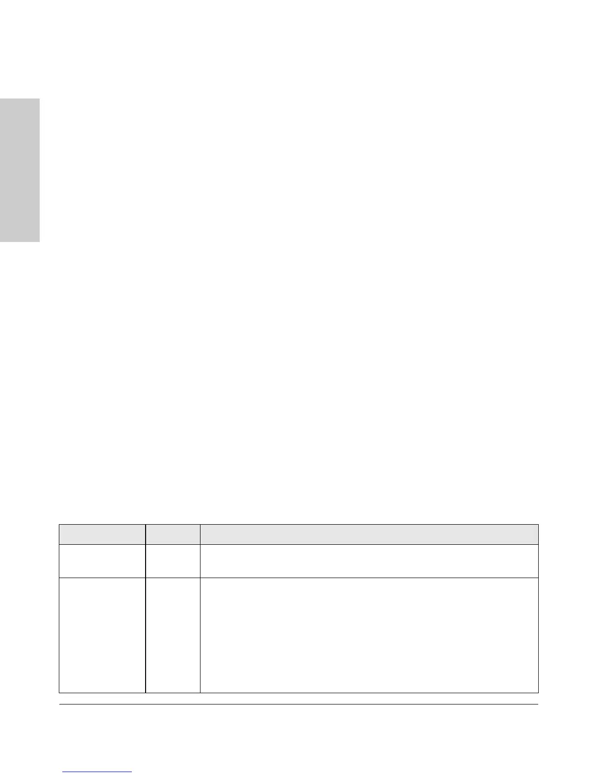
Table 1-2. Switch LEDs
Switch LEDs State Meaning
Power
(green)
On
Off
The switch is receiving power.
The switch is NOT receiving power.
Fault
(orange)
Off The normal state; indicates there are no fault conditions on the switch.
Blinking
1
A fault has occurred on the switch, one of the switch ports, module in the rear of
the switch, or the fan. The Status LED for the component with the fault will blink
simultaneously.
On On briefly after the switch is powered on or reset, at the beginning of switch self
test. If this LED is on for a prolonged time, the switch has encountered a fatal
hardware failure, or has failed its self test. See chapter 4, “Troubleshooting” for
more information.
 Loading...