2-21
Installing the Switch
Installation Procedures
Installing the Switch
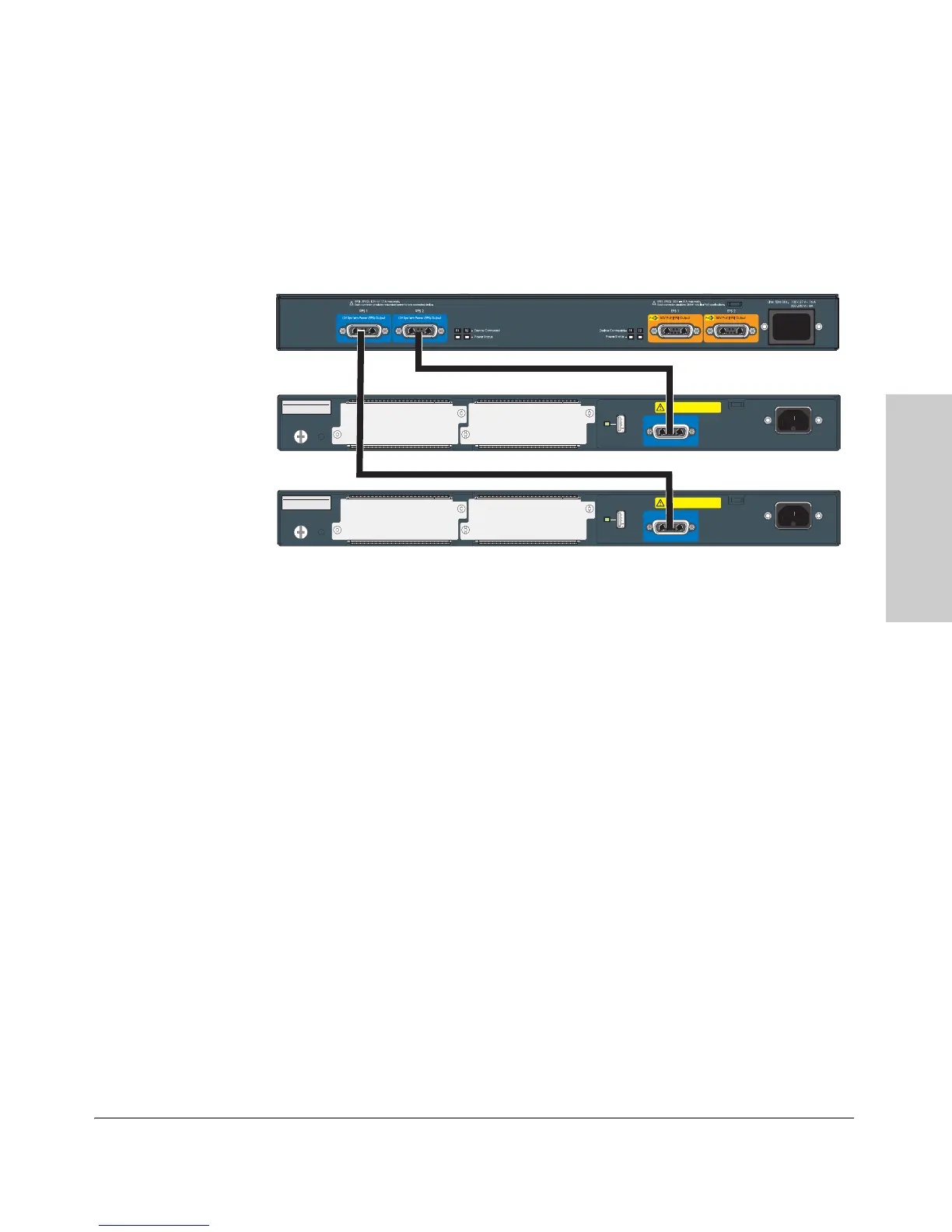
620 RPS/EPS Connectivity
This section shows some recommended connection topologies using the 620
RPS/EPS. The 620 RPS/EPS can provide backup power support for up to two
ProCurve switches. In the illustration below, two ProCurve Switch 2910s are
connected to the RPS ports on a 620 RPS/EPS.
Figure 2-16. Connecting RPS to 2 switches
9. (Optional) Connect a Console to the Switch
The switch has a full-featured, easy to use console interface for performing
switch management tasks including the following:
■ monitor switch and port status and observe network activity statistics
■ modify the switch’s configuration to optimize switch performance,
enhance network traffic control, and improve network security
■ read the event log and access diagnostic tools to help in troubleshooting
■ download new software to the switch
■ add passwords to control access to the switch from the console, web
browser interface, and network management stations
The console can be accessed through these methods:
■ Out-of-band: The switch comes with a serial cable for connecting a PC
or VT-100 terminal, to be used as a console, directly to the switch.
System MAC Address
00-01-E7-12-34-56
Serial No.
SG12345678
Line: 50/60 Hz.
100-127 V~ 10 A
200-240 V~ 5 A
12V System Power (RPS) Input
CAUTION: MULTIPLE POWER SOURCES
Disconnect AC power cord and RPS cable,
to completely remove power from the unit.
Slot
B
Slot
A
Auxiliary Port
System MAC Address
00-01-E7-12-34-56
Serial No.
SG12345678
Line: 50/60 Hz.
100-127 V~ 10 A
200-240 V~ 5 A
12V System Power (RPS) Input
CAUTION: MULTIPLE POWER SOURCES
Disconnect AC power cord and RPS cable,
to completely remove power from the unit.
Slot
B
Slot
A
Auxiliary Port
 Loading...