2-10
Installing the Switch
Installation Procedures
Installing the Switch
Verifying the Module is Installed Correctly
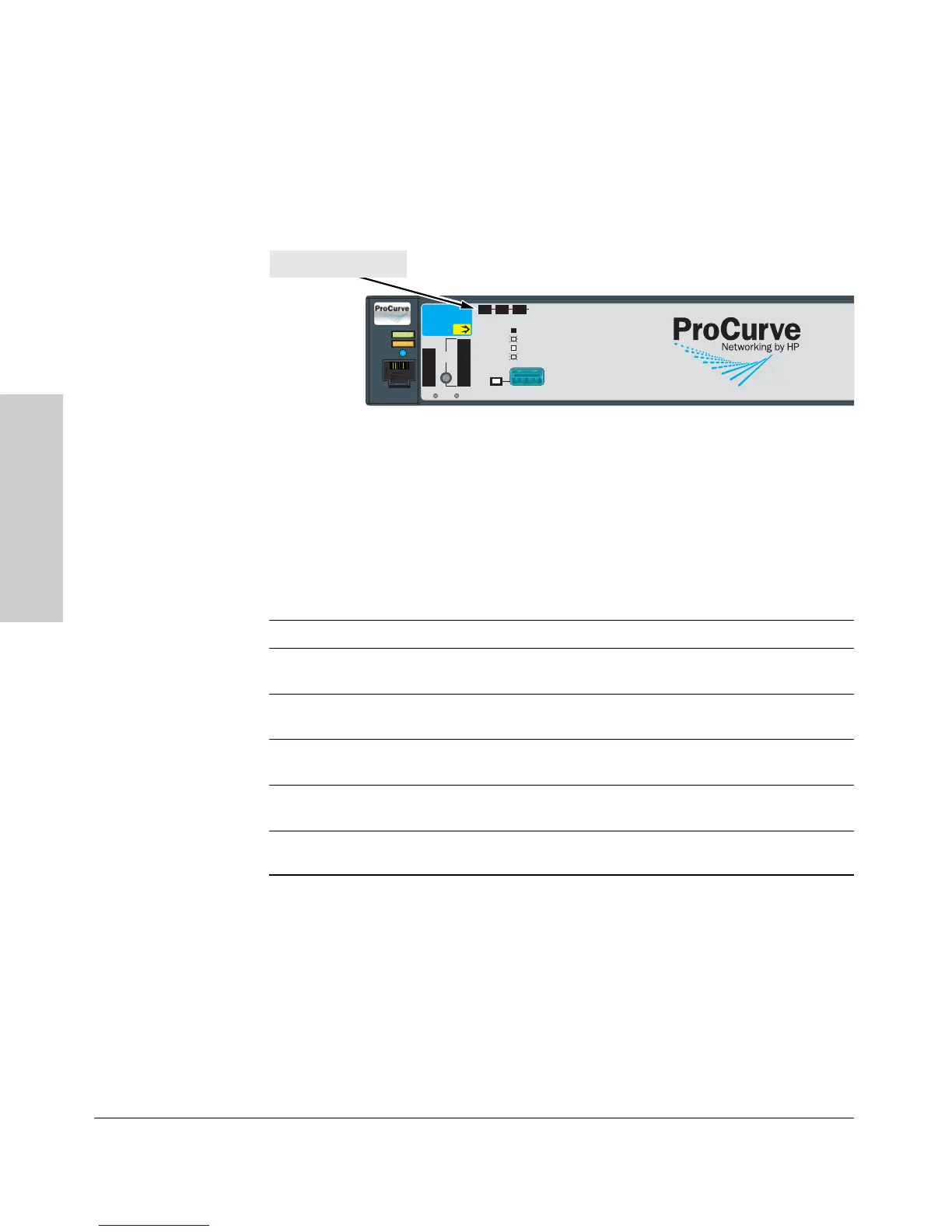
Observe the Module Status and Fault LEDs on the front of the switch to verify
the module is installed properly.
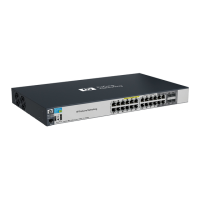
Figure 2-8. Location of Module Status LEDs
When the module is installed properly and the switch is powered on, or
the module is installed when the switch already has power, the module
undergoes a self test that takes a few seconds. You can use the LEDs to
determine that the module is installed properly and has passed the self
test, as described in the “LED Behavior” table below.
LED Behavior
LED Display for a Properly Installed Module
Mdl Status on the
front of the switch
The LED goes ON as soon as the module is installed and the switch
is powered on, and stays ON steadily.
Fault on the front of
the switch
OFF normal state, no fault condition exist.
Mdl Status on the
module
The LED goes ON as soon as the module is installed and the switch
is powered on, and stays ON steadily.
Link (on the module) The LED goes ON to indicate the port is enabled, connected and
detects a signal from the attached device.
Mode (on the module) The LED will flicker when traffic is detected on the port and the port
is transmitting and/or receiving packets.
Power
Fault
Locator
Console
Spd mode: off = 10 Mbps
2 flash = 100 Mbps
on = 1 Gbps
3 flash = 10 Gbps
*
LED
Mode
Clear
Reset
Tes t
Tmp
Status
PoE
Fan
FDx
Spd
PoE
Act
*
Status of the Back
Mdl
RPS
EPS
ProCurve Switch
2910bl-24G-PoE
J9146A
Usr
Auxiliary Port
PoE+
Module Status LED
 Loading...