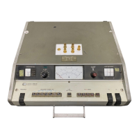
Model 4342A
Section VIII
Paragraphs 8-l to 8-5
8-l.
8-2.
a.
b.
C.
INTRODUCTION
This section includes the following:
General Notes for schematic diagrams.
Functional Overall Block Diagram (Figure 8-2).
Schematic Diagrams and Parts Location Illus-
trations.
Waveforms and voltages at indicated
test points are also included.
8-3. Circuit diagrams of Option 001 are given in
APPENDIX. Al and A5 Ass’y circuit diagrams
are
different from the Standard Model 4342A. For other
assemblies, refer to this section.
SECTION VIII
CIRCUIT DIAGRAMS
8-4. GENERAL NOTES
a. Unless otherwise indicated, resistance in ohms
capacitance in microfarads and inductance id
microhenries.
b.
C.
d.
e.
8-5.
Components assigned anasterisk (*) are factory
selected, average values shown.
(9. 4. 7) indicates wire color code. Wire color
code (MIL-STD-681) same as resistor
color
code. First number identifies ground color,
second number identifies wide stripe,
third
number identifies narrow stripe, i. e. (9. 4. 7)
denotes white ground, yellowwide stripe, violet
narrow stripe.
The components mounted on chassis or main-
frame parts are not assigned anassemblydesig-
nation (i.e. Rl, Ql, etc. ).
Reference designations (Rl, Ql, etc. ) within
assembly (Al, A2. . . .
etc. ) use assembly desig-
nation as prefix to form complete designation.
(i. e. Rl in Al assembly is AlRl)
Additional notes are shown in Figure 8-l.
P-l

 Loading...