Model 4342A List of Illustrations
LIST OF ILLUSTRATIONS
Number Title
Page
l-l.
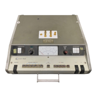
Model 4342A Q Meter . . . . . . . . . . . . . . . . . . . . . . . . . . . . . . . .
l-l
3-l.
3-2.
3-3.
3-4.
3-5.
3-6.
3-7.
3-8.
3-9.
3-10.
3-11.
Front Panel Controls
................................
3-2
Rear Panel Controls and Connectors
...................
3-4
Measurement Terminal Circuit
.......................
3-5
Inductance Measurement Ranges vs. Frequency
(direct method)
.........
3-6
Ranges of Measurable Resistance
......................
3-7
Zeroing Procedure
...................................
3-8
Distributed Capacitance in Direct Connection ........... 3-11
Distributed Capacitance Circuit Model
................. 3-13
Typical Variation of Effective Q and
Inductance with Frequency ....... 3-14
Correction Chart for Distributed Capacitance ........... 3-14
Residual Parameters .................................
3-17
4-l. Series Resonant Circuit
..............................
4-o
4-2.
Model 43426 Simplified Block Diagram
.................
4-O
4-3.
Constant Voltage Injection System
.....................
4-2
5-l.
Q Range Check
......................................
5-2
5-2.
AQ
Range Check
.....................................
5-3
5-3.
Capacitance Accuracy Check
..........................
5-4
5-4.
Model 4342A Adjustment Locations
....................
5-6
5-5.
Model 4342A Assembly Locations
...................... 5-6
5-6.
Voltmeter Adjustment
................................ 5-10
5-7.
Frequency Response Adjustment
......................
5-11
5-8.
Frequency Dial Restringing
........................... 5-15
5-9.
Main C Dial Restringing
.............................. 5-16
5-10.
AC Dial Restringing
..................................
5-17
5-11.
Tuning Capacitor Disassembly (top view) ............... 5-19
5-12.
Troubleshooting, Oscillator Section
................... 5-21
5-13.
Troubleshooting, Voltmeter Section
...................
5-19
6-l.
6-2.
6-3.
6-4.
6-5.
6-6.
6-7.
6-8.
Exploded View of Oscillator Ass’y
.....................
6-22
Exploded View of Tuning Capacitor Ass’y
.............. 6-24
Exploded View of Q Range Attenuator Ass'y
.............
6-26
Exploded View of Frequency Multiplier, Over Limit
Indicator, and Frequency Scale Indicator
..........
6-27
Exploded View of Main and Vernier Capacitor
Dial Ass’y
...... 6-28
Exploded View of Oscillator Lever Ass’y
...............
6-29
Exploded View of Rear Panel
..........................
6-30
Exploded View of Handle Section
......................
6-32
7-1. A7 04342-7707 .......................................
7-2
7-2. All 04342-7711
...................................... 7-2
7-3.
Partial Schematic of Power Supply
.................... 7-5
8-1.
Schematic Diagram Notes . .
. . . . . . . . . . . . . . . . . . . . . . . . . . 8-2
8-2.
Function Overall Block Diagram
. . . . . . . . . . . . . . . . . . . . . . 8-3
8-3.
Oscillator
Ass'y Al,
Q Range Attenuator
Ass'y A3,
Power Supply & ACL Amplifier Ass’y A8,
Frequency Multiplier & Over Limit Indicator
Ass'y
AlO.. 8-5

 Loading...