Display panel assembly
WARNING! To reduce risk of personal injury from hot surfaces, allow the internal system components to
cool before touching.
1. Prepare the computer for disassembly (Preparation for disassembly on page 19).
2. Remove the front panel (
Front panel on page 31).
3. Remove the USB assemblies (
USB port assembly on page 44).
4. Remove the speakers (
Speakers on page 47).
5. Remove the top system board bracket (
System board on page 52).
6. Remove the antennas and transceivers (
Antennas and transceivers on page 50).
NOTE: You have to remove the antenna transceivers to move the top system board bracket. You need
only to move the bracket aside when removing the display panel assembly.
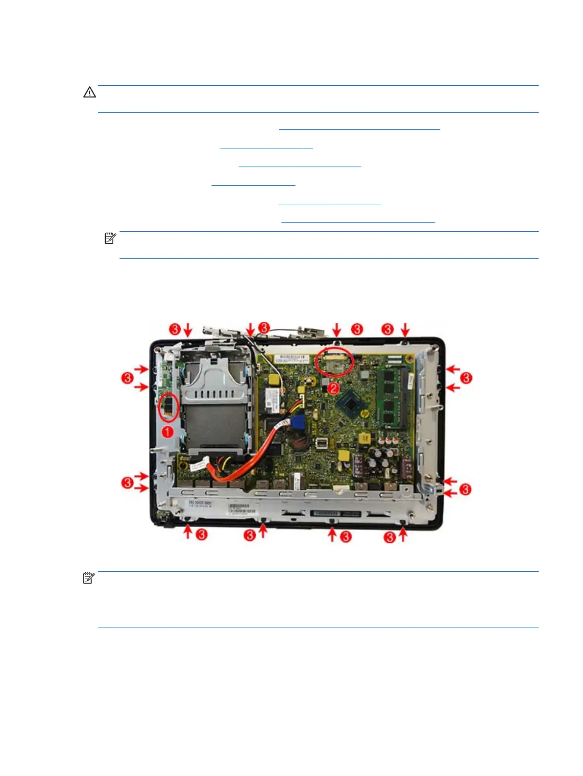
7. Disconnect the cable from the touch board (1).
8. Disconnect the display cable from the system board (2).
9. Remove the 16 Torx screws (3) that secure the display panel assembly to the main computer bracket.
10. Lift the bracket off the display panel assembly.
NOTE: For R-touch models, the display panel assembly includes a resistive touch board that is pre-
programmed to the touch glass and mounted separately to the chassis. Be sure to use the same board this is
supplied with the replacement display. Do not mix and match panels and touch boards.
The P-Cap board is mounted on the display panel rear side.
To replace the display panel assembly, reverse the removal procedures.
Display panel assembly 57
 Loading...