Display assembly
NOTE: The Dream Color display assembly is spared as a whole unit assembly only. The LED display assembly
is spared at the subcomponent level only. For more LED display assembly spare part information, see the
individual removal subsections.
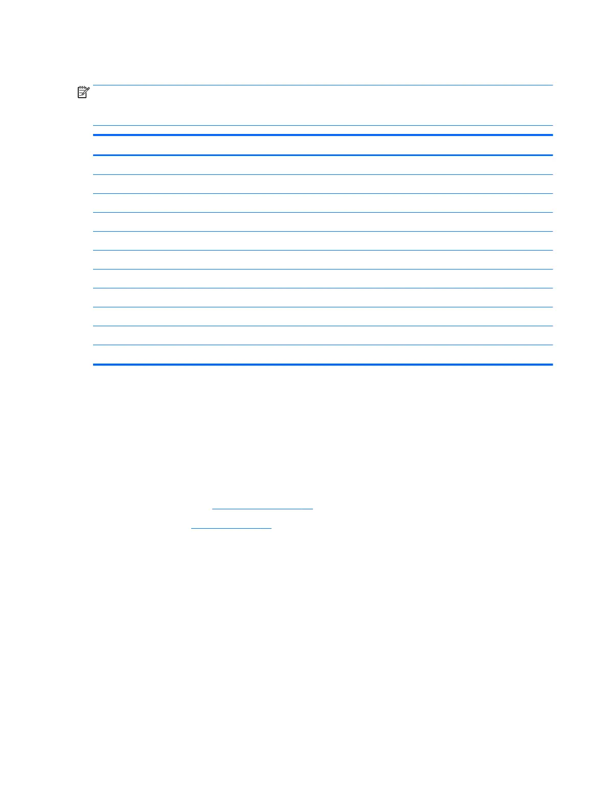
Description Spare part number
17.3 FHD, UWVA AG with camera and touch screen 921322-001
17.3 in UHD, Dream Color 3 UWVA 921323-001
17.3 in UHD, Dream Color 3 UWVA f/camera 921324-001
Raw panel 17.3 FHDAGWLEDUWVA300eDP Flat AK 819347-002
Raw panel 17.3 HD+AGWLEDSVA 220eDP Flat AK 819348-002
Hinge 906120-001
LCD bezel with magnet 848368-001
Bezel with camera 850119-001
LCD cable 848379-001
Webcam, 1p DM U2 Mjpeg 720p CTS Vaughn 819336-006
Microphone board 854110-001
To remove the display assembly and access the LED display assembly subcomponents, follow these steps:
1. Turn o the computer. If you are unsure whether the computer is o or in Hibernation, turn the
computer on, and then shut it down through the operating system.
2. Disconnect the power from the computer by unplugging the power cord from the computer.
3. Disconnect all external devices from the computer.
4. Remove the following components:
a. Service door (see Service door on page 30).
b. Battery (see Battery on page 31).
Remove the display assembly:
1. Remove the six Phillips screws (1) that secure each hinge to the computer.
2. Open the computer as far as possible.
68 Chapter 6 Removal and replacement procedures for authorized service provider parts
 Loading...