5.7.5 Connecting the NS Protection Signal Cable
Connecting the Inverter to the NS Protection Signal Cable
● The NS protection function applies to areas in compliance with the VDE 4105 standard,
and the grid code needs to be set to VDE-AR-N-4105 or SWITZERLAND-NA/EEA:2020-
LV230.
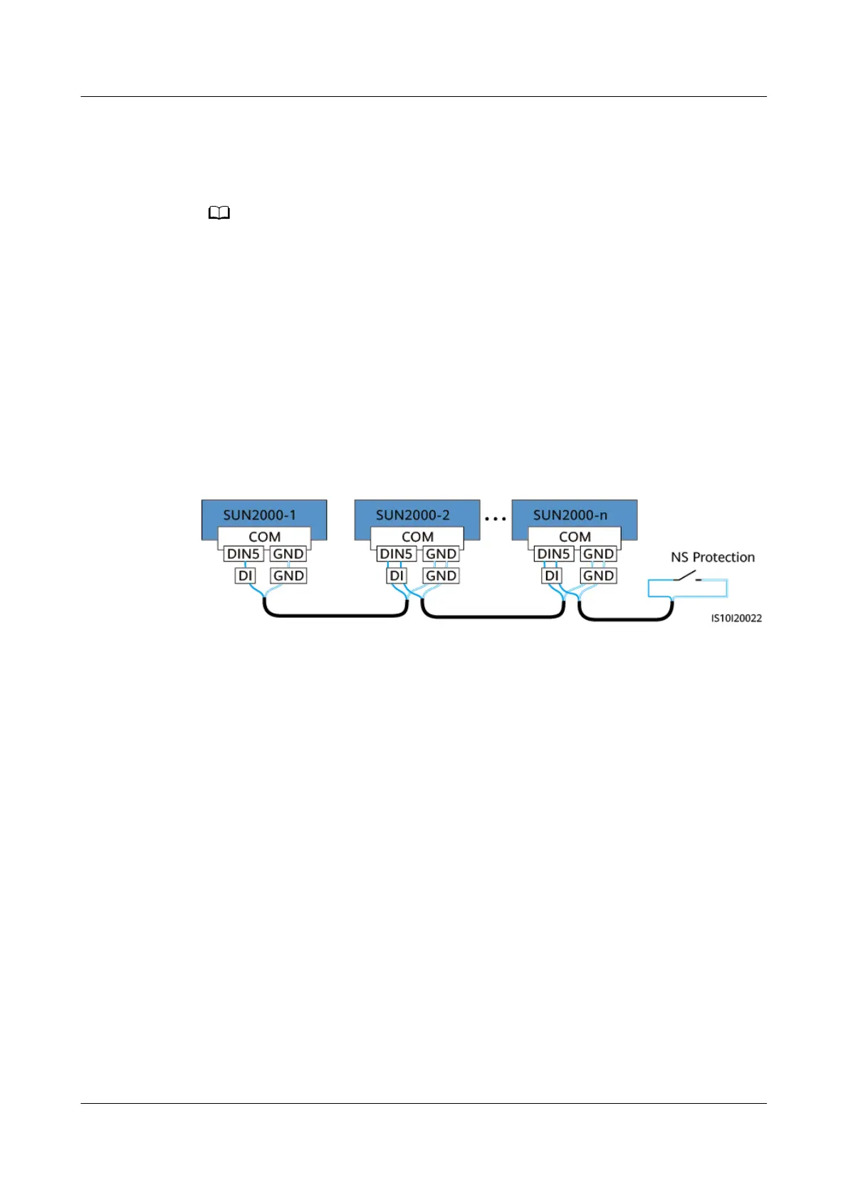
● The NS protection switch is connected to GND (pin 13) at one end and to DIN5 (pin 15)
at the other end. The switch is turned
o by default. When the switch is turned on, NS
protection is triggered. Rapid shutdown and NS protection use the same pins, which are
GND (pin 13) and DIN5 (pin 15). Therefore, you can use only one of the functions.
● The NS protection switch connection is the same for a single inverter and for cascaded
inverters.
● Log in to the FusionSolar App as an installer, choose My > Device Commissioning, and
connect to the WLAN hotspot of the SUN2000. Log in to the local commissioning
system as an installer user, choose Settings > Feature parameters > Dry contact
function, and set Dry contact function to NS protection.
Figure 5-36 Connecting cascaded inverters to the NS protection switch
Step 1 Connect the signal cables of the cascaded inverters to the signal cable connectors.
SUN2000-(8KTL-20KTL)-M2
User Manual 5 Electrical Connections
Issue 11 (2023-02-07) Copyright © Huawei Technologies Co., Ltd. 67
 Loading...