20 ArcGlide THC Replacement Parts Field Service Bulletin 806560
2 – Replacing ArcGlide parts
To replace the display board:
1. Fit
the new LED board over the standoffs with the 34-pin connector at the top.
2. Replace the threaded standoff and washer in the upper left corner of the board. Tighten the standoff to 0.90 N·m
(8 lb·in.).
3. Replace the 3 screws in the remaining standoffs. Tighten the screws to 1.13 N·m (10 lb·in.).
4. Insert the connector for the ribbon cable in the 34-pin connector on the board.
Use the following procedure to replace additional parts:
228581 – HMI processor board on page 18
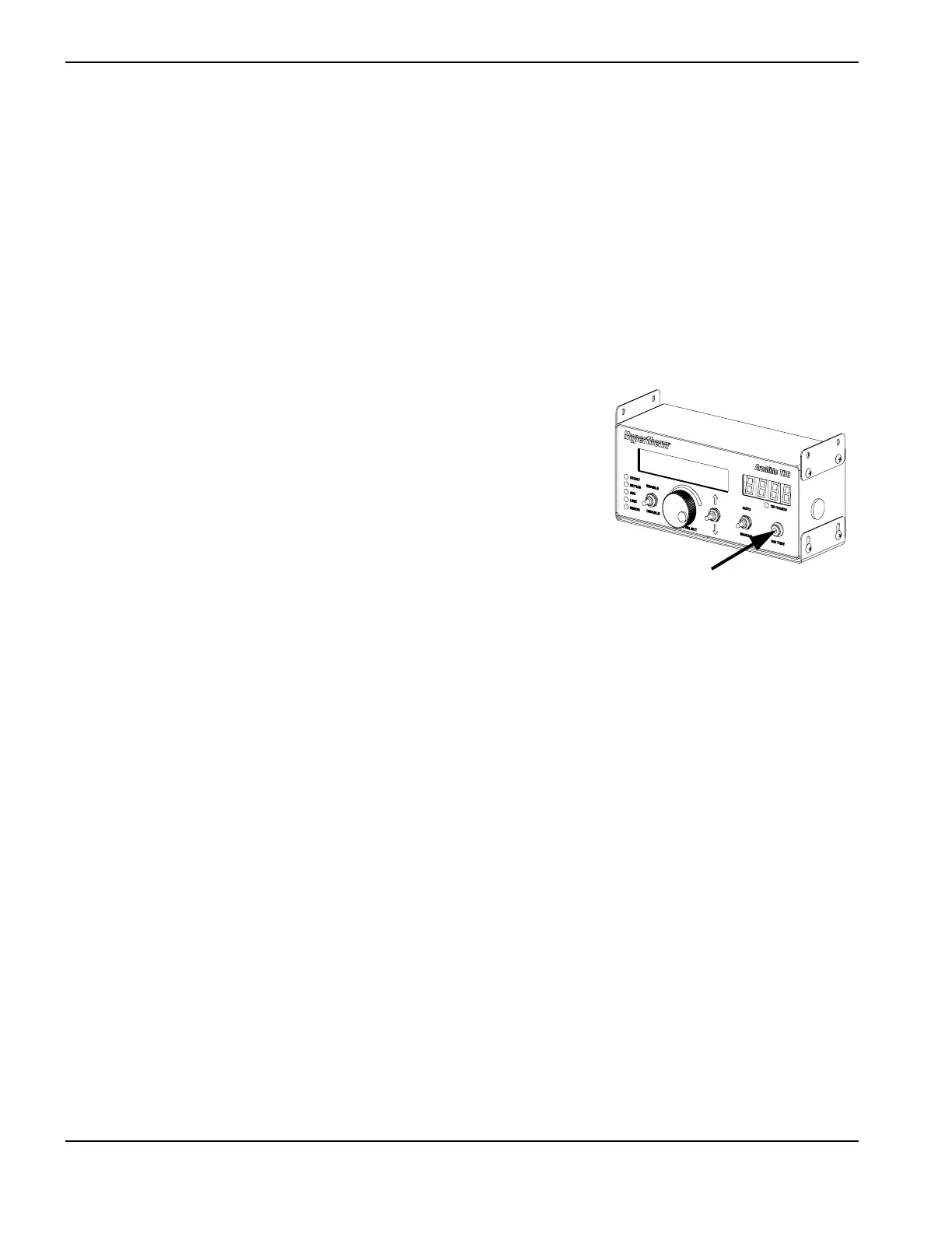
228583 – Momentary pushbutton switch
Follow the steps in Accessing HMI parts on page 12 to open the rear panel of
the HMI enclosure. Set aside all screws and other hardware for reuse.
To access the momentary pushbutton switch, you must use the following
proce
dure to remove additional parts:
228581 – HMI processor board on page 18
To remove the momentary pushbutton switch:
1. Remove the
14-mm hex nut from the back of the switch on the inside of the front panel.
2. Remove the switch from the front of the front panel.
To replace the momentary pushbutton switch:
1. T
hread the cable for the replacement switch through the switch opening in the front panel.
2. Replace the hex nut around the base of the switch and tighten it to 1.35 N·m (12 lb·in.).
Use the following procedures to remove and replace additional parts:
228581 – HMI processor board on page 18

 Loading...
