ArcGlide THC Replacement Parts Field Service Bulletin 806560 29
2 – Replacing ArcGlide parts
To replace the power source:
1. Place
the new board over the standoffs with the larger connector on the side of the transformer (in the control
module) or the line filter (in the HMI).
2. Fasten the screws into the standoffs. Tighten the screws to 0.67 N·m (6 lb·in.).
3. Replace the connectors for the red and black wires and the black and white wires.
4. Replace the rear panel and fasten the screws. Tighten the screws to 1.13 N·m (10 lb·in.).
228591 – Lifter slide
The procedure to replace the lifter slide must be performed by trained technicians.
Improper assembly can result in binding and alignment problems with
the proximity switches and the laser pointer.
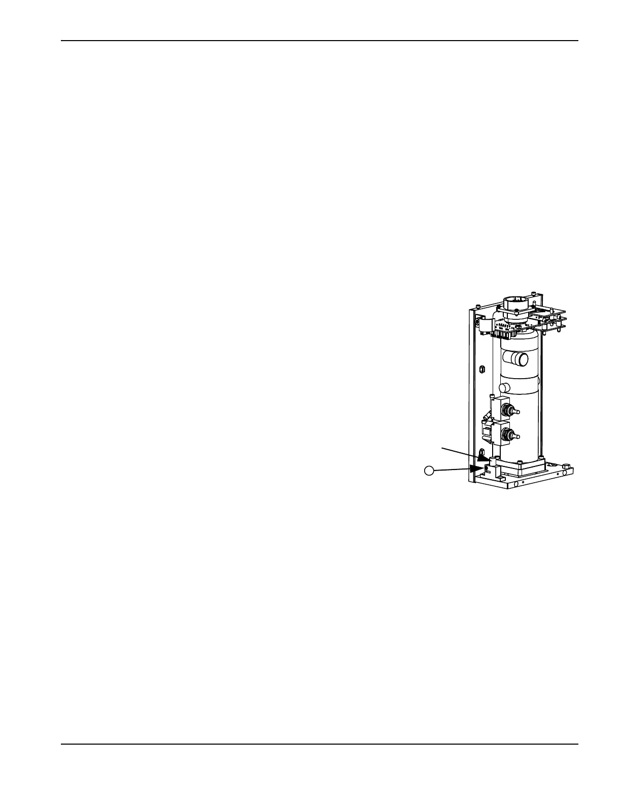
228592 – Laser pointer diode
Follow the steps in Accessing lifter parts on page 12 to open the front cover of
the motor enclosure. Set aside all scre
ws and other hardware for reuse.
To remove the laser pointer diode:
1. Cut t
he cable ties that secure the laser diode wires.
2. Remove the cable connector from J7 on the lifter interface board.
3. Loosen, but do not remove, the screw on the outside of the bracket for the
laser pointer.
4. Pull the pointer from the bracket.
To replace the laser pointer diode:
1. Push the new pointer to the bottom of the bracket. The bracket automatically aligns the laser.
2. Tighten the screw in the pointer bracket to 0.22 N·m (2 lb·in.).
3. Reconnect the diode cable connector to J7 on the lifter interface board.
4. Secure the diode cable connector with cable ties to the cable anchor on the enclosure.
5. Replace the front cover of the motor enclosure and fasten the 4 screws. Tighten the screws to 1.13 N·m (10 lb·in.).

 Loading...
