MAX200 Instruction Manual 4-3
1-97
OPERATION
Status Indicators Before Startup
When Power is applied from the line disconnect switch and before the POWER ON (I) button is pushed, the
COOLANT FLOW LED will be illuminated. Once the POWER ON button is pushed, this LED will extinguish if the
system is in the proper working condition. Other fault conditions may also be indicated when the line power is
switched on. Correct any other fault conditions before pressing the the POWER ON (I) button. See Troubleshooting
in Section 3 of MAX200 Service Manual, IM-162 (801620).
Gas
• TEST/RUN switch
Sets dynamic (flowing) gas flow.
• PLASMA pressure gauge/plasma gas needle valve
Adjusts and displays the plasma gas flow pressure.
• SHIELD pressure gauge/shield gas needle valve
Adjusts and displays the shield gas flow pressure.
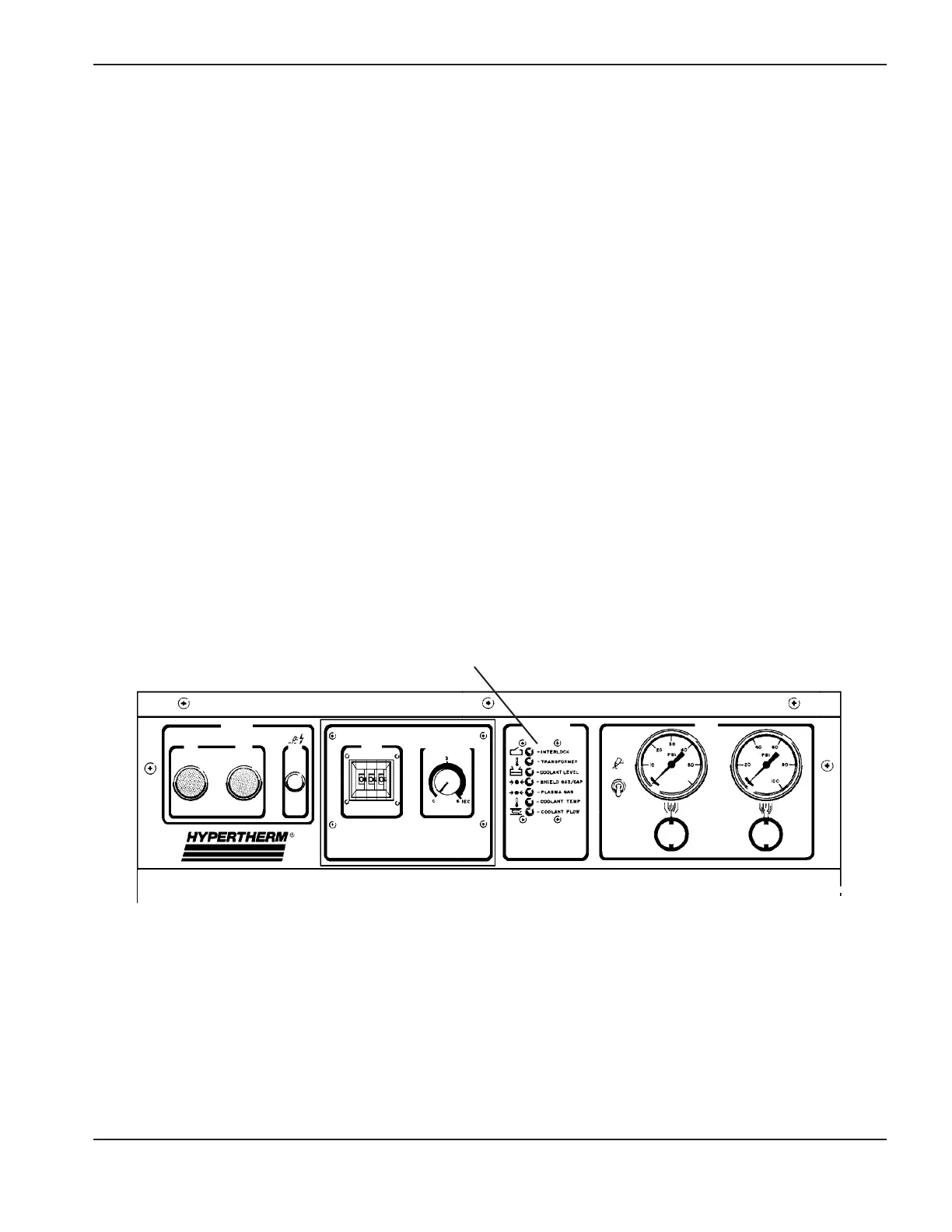
Figure 4-1 Front Panel Controls
I
ON
0
OFF
POWER
DC ON
AMPS
STATUS
RUN
TEST
GAS
PLASMA SHIELD
- INTERLOCK
- TRANSFORMER
- COOLANT LEVEL
- SHIELD GAS/CAP
- PLASMA GAS
- COOLANT TEMP
- COOLANT FLOW
MACHINE DELAY
 Loading...