19
OPERATING INSTRUCTIONS
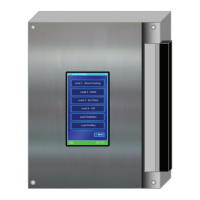
V-10 TOUCH SCREEN BOILER CONTROLLER
NOTE
Location of the indoor
temperature sensor is very
important. Typically the
sensor needs to be installed
in the coolest area of the
space being heated.
Heating settings screen. To increase heat (e.g. From 72°F/22°C to 74°/23°C)
- move the Indoor Setpoint ° value upward (warmer) from the level otherwise
chosen. This shifts the position of the reset curve, will amend the boiler water
temperature by a similar amount. Do not adjust the Design Indoor ° value - a
movement upward in concert with the Indoor Setpoint ° adjustment will have the
effect of neutralizing the intended effect.
An optional indoor temperature feedback routine can be activated with the
installation of an indoor sensor, connected to the designated TB2 contacts to
automate adjustment of the outdoor reset routine.
The key inputs on initial set up are (1) Design Outdoor ° – the coldest expected
outdoor temperature typically experienced at the installation site; (2) the Design
Supply ° – the desired boiler outlet temperature to occur at that coldest day; and
(3) the Design Indoor ° - this is the temperature value that anchors the reset
curve. The Indoor Setpoint ° setting is the primary means for the user to “bias”
the outdoor reset routine to add or reduce heat.
If Reset Heating is selected and there is no signal received from the Outdoor
Sensor, the controller assigns a provisional 32°F/0°C value and will adopt the
appropriate temperature target from the relevant reset curve.
Use the Minimum Supply ° entry to optimize boiler run times on low mass loads.
Finned tube baseboards sink very little heat when operated below 90° F/32°C;
application of a “full reset curve” (e.g. 160°F/71°C right down to a 70° F/21°C
room target) would cause boiler cycling in light-to-moderate heating conditions.
Set baseboard minimums at 90-120°F (32-49°C) and aim for 4 or less cycles/
hr. A minimum setting can also be used to enhance home comfort with single
or excessive speed air handlers to avoid the cool blast effect. Set to the lowest
possible level for combustion efciency.
1.7.4 Temperature Differential Settings
For all loads, the Maximum Supply ° and the on/ off Supply Diff’l ° temperature
settings should be reviewed to ensure the Maximum takes account of the
construction and safety requirements of each application – e.g., 140°F/60°C
maximum for typical in-slab radiant oor, for avoidance of thermal stress. The
Supply Diff’l ° shall be set to offer a reasonable temperature control range
(suggested values: 20°F/11°C for high mass radiant // 10°F/6°C for DHW). Ensure
that the spread between the target and maximum temperatures is greater than one
half of the Supply Differential temperature. For example, for a radiant oor a Design
Supply temperature of 125°F and a High Limit or Maximum Supply of 140°F, and a
differential (Supply Diff’l °) setting of 20°F (half of which is 10°F) ts nicely.
1.7.5 Daily Temperature Overrides
This feature provides the ability to override set point temperatures for each Load
for specic programmable time periods for each day of the week. Normally this
feature is used to reduce temperatures during night-or-away hours to achieve
fuel savings. The feature can also increase temperatures for dened time periods
in a day; this may be of use for certain commercial applications where short-term
high temperature DHW service is desired.
 Loading...