21
OPERATING INSTRUCTIONS
V-10 TOUCH SCREEN BOILER CONTROLLER
1.7.8 External Control
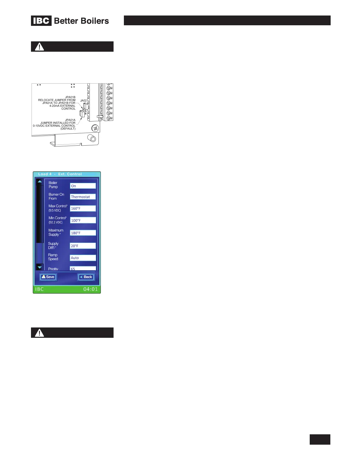
Installers have the option of placing the control of a load under an external
electronic controller (such as a tekmarNET © control). Connections are
provided (TB2 Ext. Cont.) to receive a 0-10VDC or 4-20 mA signal for throttle
management. The default conguration is 0-10VDC (JPA01A installed); to switch
over to 4-20 mA (JPA01B installed), disconnect electrical power to the boiler,
remove the electrical box corner cover and the circuit board cover to provide
access to jumpers on the lower right corner of the control circuit board; use
needle-nose pliers to place the plastic jumper tabs as pictured in the adjacent
drawing. Reinstall cover then restore power to the boiler.
When the IBC controller senses a signal on the remote connections, it
automatically subordinates its internal throttle logic, and adopts the external
signal. The burner on/off, or the call for heat, can be set to the thermostat input
or the Ext. Control input. In remote mode, temperature management is also
surrendered to the external controller’s sensors. The installer enters maximum
boiler supply and on/off differential temperatures; the boiler will respond to these
as high limit switches.
From the Installer Settings screen, touch the Entry Button corresponding to the
desired load and select Ext. Control, then congure the load with the maximum
and differential temperature values. Externally controlled loads work with other
loads with the same priority, logic and sequencing.
1.7.9 Alarm Contacts
The controller provides a relay dry contact connection to indicate the boiler’s
alarm state externally. This can be used, for example, to connect to an external
alarm panel or indicator light. The terminals on TB3 supply the wiring connection.
Disconnect electrical power to the boiler, remove the controller front cover to
access the TB3 connection. Refer to the diagrams in Section 2 for more details.
The alarm contacts will normally be open indicating no alarm present. The
contacts will be closed any time an alarm state is present and boiler operation
has been disabled. This corresponds to when the boiler status bar on the display
is red. The error that was detected creating the alarm state will be recorded in the
Error Log and will be displayed in the boiler status bar.
1.7.10 Multi-Boiler Operation
The Multi-Boiler capability allows a group of up to 24 IBC boilers to be
connected and networked together to operate as a single heating plant. The
boilers are networked for communication and control via a proprietary network
called BoilerNet.
Boilers can be congured for Multi-Boiler operation using the Multi-Boiler
Settings screen available by selecting Multi-Boiler from the Installer Settings
menu. Please refer to the latest IBC Technical document on Multiple Boiler
Systems for detailed information on how to set the parameters involved for
proper Multi-Boiler operation.
NOTE
Consult IBC’s latest technical
memorandum on multi-
boiler operation prior to
implementing any multiboiler,
multi-load application
NOTE
Disconnect electrical power
to the boiler before removing
the circuit board cover.
 Loading...