OPERATING INSTRUCTIONS
22
V-10 TOUCH SCREEN BOILER CONTROLLER
The BoilerNet Interface utilizes a 2-wire CAN-bus communications interface
between the boilers. BoilerNet wiring must be installed in compliance with the
published standards, ISO 11898 or SAE J2284. A suitable cable, compliant with
the same standards must be used.
The general specications for this cable are:
• 24 AWG shielded twisted pair
• 9 twists / ft
• Capacitance 12.5pF/ft (cond./cond.)
• Resistance 25.5 ohms/1000 ft
Network wiring tips:
• The “Boiler Net +” and “Boiler Net –“ are polarity sensitive and must not be
crossed.
• The Boiler Network wiring must only be installed in a “Daisy Chain” format
where the network wiring goes from the rst boiler to the second to the third to
the fourth and so on.
• When using shielded pair wire ensure the shielding is only grounded at one
end of the “Daisy Chain”. If the shielding is grounded in multiple locations (i.e.
at each boiler or at the rst and last boiler,) the shielding becomes ineffective
and in some cases increases the electromagnetic interference affecting the
communication signal.
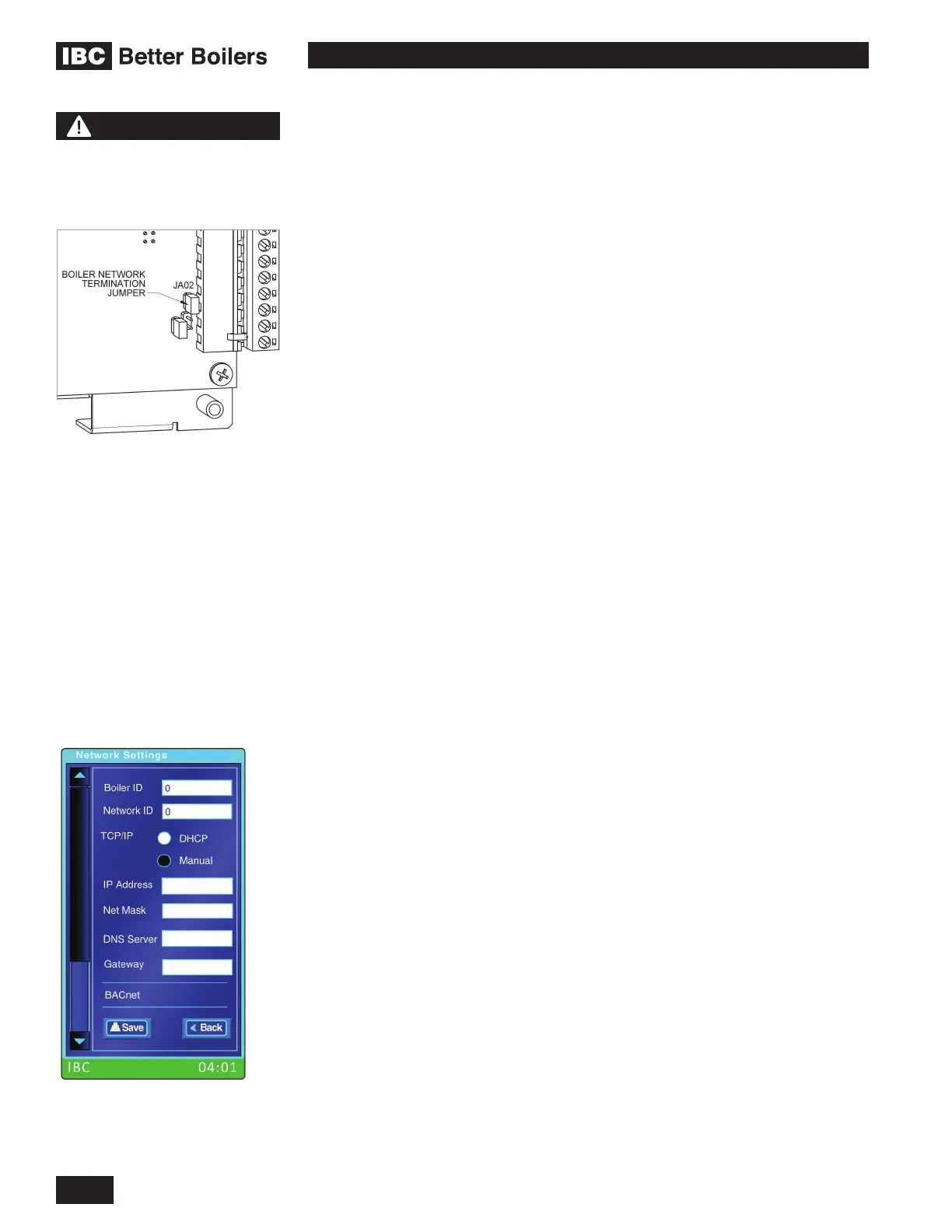
The termination jumper (JA02) needs to be removed from the boiler controller
boards that are NOT the rst or last boiler of the BoilerNet chain. For example, in
a two boiler network JA02 must be left installed in both controllers and in a three
boiler network the JA02 must be removed on the middle boiler only.
Please contact IBC if any additional information is required.
1.7.11 Internet Networking
Internet Protocol (IP) networking based features are supported via the standard
RJ 45 Ethernet jack on the back of the controller board. Web Browser access for
set up, monitoring and control of the boiler and BACnet capabilities are examples
of features enabled by connecting the controller to an IP network via the Ethernet
jack.
The IP network settings are available via the Network Settings selection on the
System Settings screen (see section 1.5.5.2). On the Network Settings screen
the TCP/IP group of parameters includes the basic settings required to connect
to an IP network. By default DHCP is selected. When DHCP is activated the
other four entries are not required and their entry boxes are disabled. When
the particular installation requires that the boiler be assigned a xed IP address
then Manual must be selected and the boiler’s IP Address, the Net Mask, DNS
Server address and Gateway address must be entered manually.
The controller supports standard 100 Base T data rates over typical CAT5
or CAT6 wiring. Connection to wireless networks can be supported using an
inexpensive wireless access point device connected to the Ethernet jack. The
wireless access point device must be congurable to operate in client mode.
Contact IBC for currently available access point device suggestions.
WARNING
Disconnect electrical power
to the boiler before removing
the circuit board cover.
 Loading...