START
MAP
PAGE
2
OF
4
(CONTINUED
)
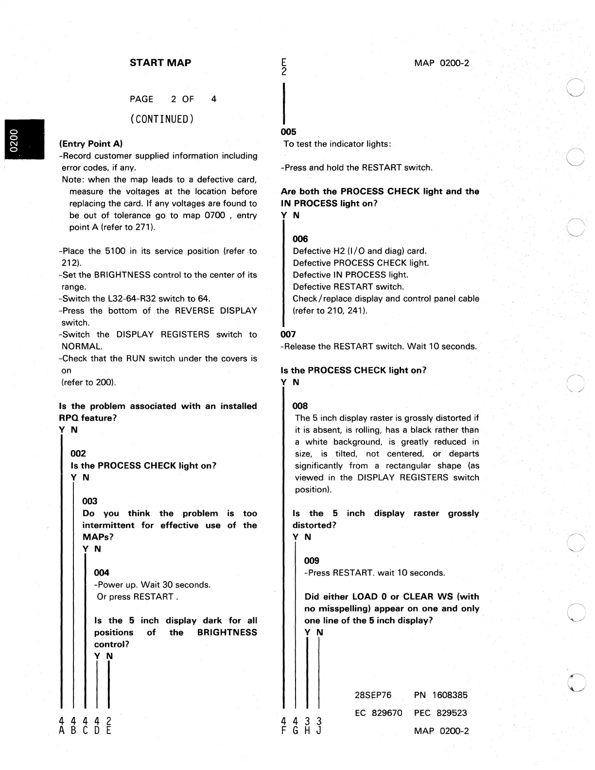
(Entry
Point
A)
-Record customer supplied information including
error codes,
if
any.
Note: when the map
l€lads
to a defective card,
measure the voltages at the location before
replacing the card.
If
any voltages are found
to
be
out
of
tolerance go
tp
map 0700 , entry
point A (refer
to
271).
-Place the 5100 in its service position (refer ,to
212).
-Set the BRIGHTNESS control
to
the center
9f
its
rang€l.
-Switch the L32-64-R32 switch
to
64.
-Press the bottom
of
the
REVERSE
DISPLAY
switch.
-Switch the DISPLAY REGISTERS switch
to
NORMAL.
-Check that the
RUN
switch under the covers
is
on
(refer
to
200).
Is
the
problem
associated
with
an
installed
RPQ feature?
Y N
002
Is
the
PROCESS CHECK
light
on?
Y N
003
Do
you
think,
the
problem
is
too
intermittent
for
effective
use
of
the
MAPs?
Y N
004
-Power up.
Wait
30 seconds.
Or press RESTART.
Is
the
5
inch
display
dark
for
all
positions
of
the
BRIGHTNESS
control?
Y N
4 4 4 4 2
ABC
0 E
E
2
MAP
0200-2
005
To test the indicator lights:
-Press and hold the RESTART switch.
Are
both
the
PROCESS CHECK
light
and
the
IN
PROCESS
light
on?
Y N
006
Defective H2
(I/O
and diag) card.
Defective
PROCESS
CHECK light.
Defective
IN
PROCESS
light.
Defective RESTART switch,
Check/
replace display and control panel
cabl,e
(refer
to
210, 241).
007
-Release the RESTART switch.
Wait
10 seconds.
Is
the
PROCESS CHECK
light
«)I'l?
Y N
008
The 5 inch display raster is grossly distorted if
it is absent. is rolling, has a black rather
thl'lM
a white background,
is
greatly reduced
i,n
size,
is
tilted, not centered, or departs
significantly from a rectangular shape
(as
viewed
in
the DISPLAY
REGISTERS
switch
position),
Is
the
5
inch
displl;ly
raster
grossly
distorted?
Y N
009
-Press
RESTART.
wait 10 seconds.
Did
either
LOAD 0
or
CLEAR
WS
(with
no
misspelling)
appear
on
one
arid
only
one line
of
the
5
inch
display?
Y N
4 4 3 3
F G H J
28SI=P76
PN
1608385
EC
829670 PEe az9523
MAP 0200-2
c
c
 Loading...