(
(
(
(
(-
DISPLAY
MAP
0500
PAGE 1
OF
10
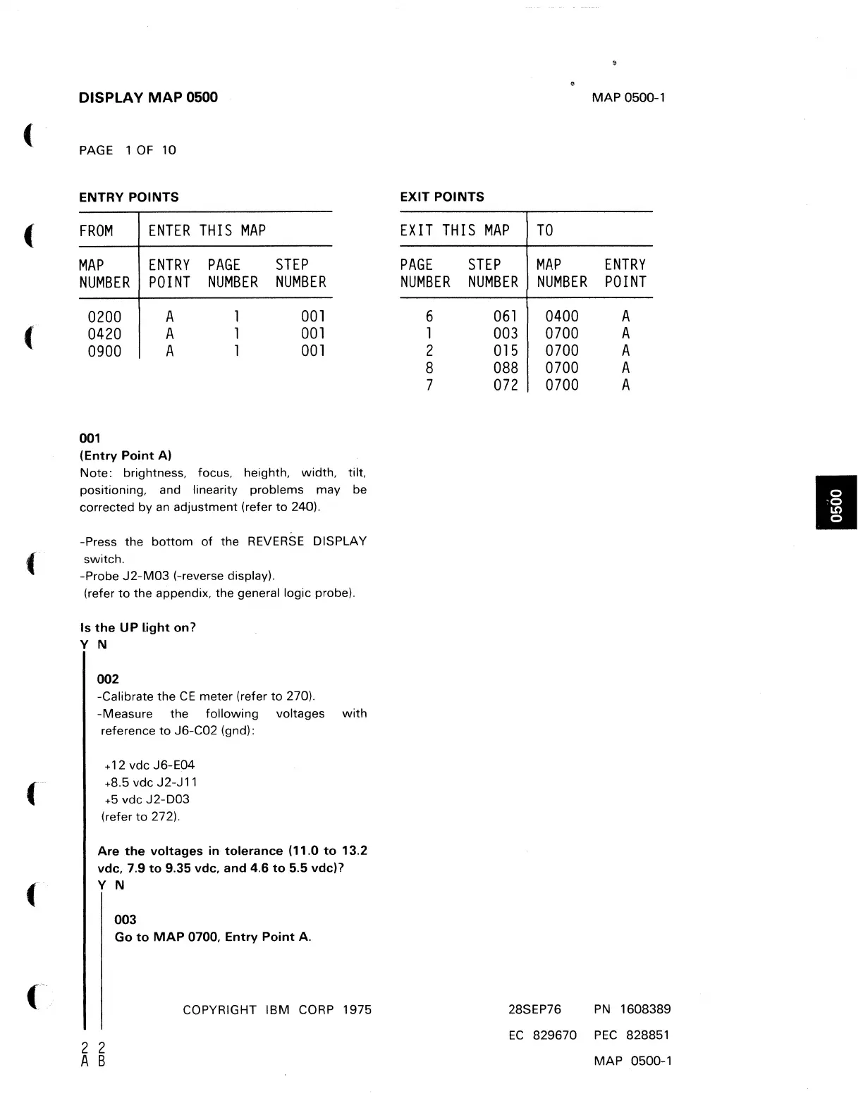
ENTRY
POINTS
FROM
ENTER
THIS
MAP
MAP
ENTRY
PAGE
STEP
NUMBER
POINT
NUMBER
NUMBER
0200
A
001
0420
A
001
0900
A
001
001
(Entry
Point
A)
Note: brightness, focus, heighth, width, tilt,
positioning, and linearity problems may be
corrected by
an
adjustment (refer
to
240).
-Press the
bottom
of
the
REVERSE
DISPLAY
switch.
-Probe
J2-M03
(-reverse display).
(refer
to
the appendix, the general logic probe).
Is
the
UP
Light on?
Y N
002
-Calibrate the
CE
meter (refer
to
270).
-Measure the following voltages
with
reference
to
J6-C02
(gnd):
+ 12 vdc J6-E04
+8.5 vdc J2-J11
+5
vdc
J2-D03
(refer
to
272).
Are
the
voltages
in
tolerance
(11.0
to
13.2
vdc.
7.9
to
9.35
vdc.
and
4.6
to
5.5
vdc)?
Y N
003
Go
to
MAP
0700.
Entry
Point
A.
2 2
A B
COPYRIGHT IBM CORP 1975
MAP
0500-1
EXIT
POINTS
EXIT
THIS
MAP
TO
PAGE
STEP
MAP
ENTRY
NUMBER
NUMBER
NUMBER
POINT
6
061
0400
A
1
003
0700
A
2
015
0700
A
8
088
0700
A
7
072
0700
A
28SEP76
PN
1608389
EC
829670
PEC
828851
MAP
0500-1
I
 Loading...