(
(
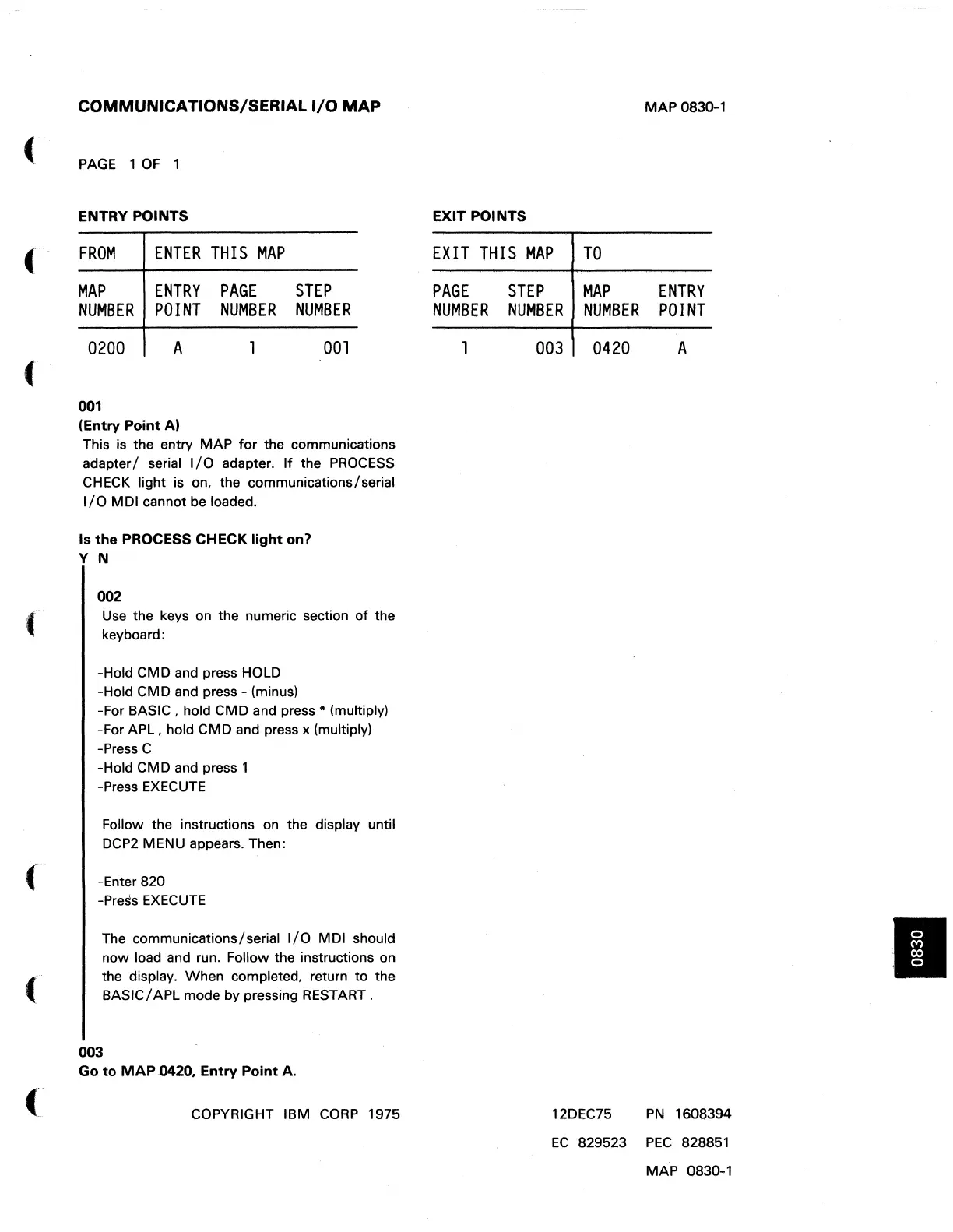
COMMUNICATIONS/SERIAL
I/O
MAP
PAGE
1
OF
1
ENTRY POINTS
FROM
ENTER
THIS
MAP
MAP
NUMBER
ENTRY
POINT
PAGE
NUMBER
STEP
NUMBER
0200
A
001
001
(Entry
Point
A)
This is the entry MAP
for
the communications
adapter / serial
I/O
adapter.
If
the
PROCESS
CHECK light is on. the communications/serial
I/O
MDI cannot be loaded.
Is
the
PROCESS CHECK
light
on1
Y N
002
Use
the keys on the numeric section
of
the
keyboard:
-Hold CMD and press HOLD
-Hold CMD and press - (minus)
-For BASIC. hold CMD and press
* (multiply)
-For
APL.
hold CMD and press x (multiply)
-Press C
-Hold CMD and press 1
-Press
EXECUTE
Follow the instructions on the display until
DCP2
MENU appears. Then:
{ -Enter 820
-Press
EXECUTE
The communications/serial
I/O
MDI should
now load
and
run. Follow the instructions on
the display. When completed. return
to
the
BASIC/APL mode by pressing RESTART.
003
Go
to
MAP
.0420,
Entry
Point
A.
COPYRIGHT IBM
CORP
1975
EXIT POINTS
EXIT
THIS
MAP
PAGE
NUMBER
1
STEP
NUMBER
003
TO
MAP
NUMBER
0420
12DEC75
MAP
0830-1
ENTRY
POINT
A
PN
1608394
EC
829523
PEC
828851
MAP 0830-1
•
 Loading...