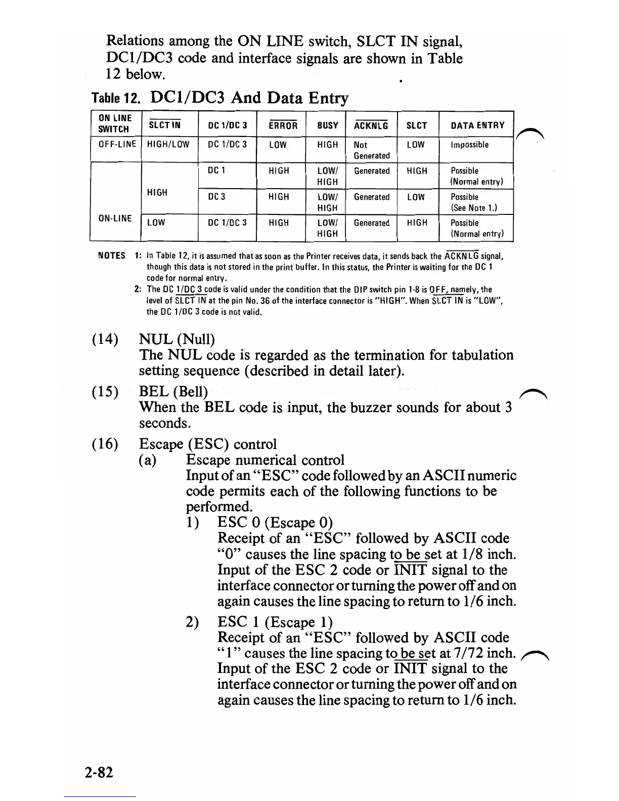
Relations among the
ON
LINE
switch, SLCT
IN
signal,
DC1/DC3
code and interface signals are shown in Table
12 below.
Table
12.
DCl/DC3
And
Data
Entry
ON
LINE
SLCTIN
DC
llDC
3
ERROR
BUSY
ACKNLG
SLCT
DATA
ENTRY
SWITCH
OFF-LINE
HIGHILOW
DC
llDC
3
LOW
HIGH
Not
LOW
Impossible
Generated
DC
I
HIGH
LOWI
Generated
HIGH
Possible
HIGH
(Normal
entry)
HIGH
DC
3
HIGH
LOWI
Generated
LOW
Possible
HIGH
(See
Note
1.)
ON-LINE
LOW
DC
llDC
3
HIGH
LOW/
Generated
HIGH
Possible
HIGH
(N
ormal
entry)
NOTES
1:
In
Table
12,
it
is
assumed
that
as
soon
as
the
Printer
receives
data,
it
sends
back
the
ACKNLG
signal,
though
this
data
is
not
stored
in
the
print
buffer_
In
this
status,
the
Printer
is
waiting
for
the
DC
I
code
for
normal
entry_
2:
The
DC
I/OC
3
code
is
valid
under
the
condition that
the
DIP
switch
pin
1-8
is
OFF,
namely,
the
level
of
SLCT
IN
at the
pin
No_
36
of
the
interface connector
is
"HIGH"_
When
SLCT
IN
is
"LOW",
the
DC
I/DC
3
code
is
not
valid.
(14)
NUL
(Null)
The
NUL
code is regarded
as
the termination for tabulation
setting sequence (described in detail later).
(15)
BEL
(Bell)
~
When the
BEL
code
is
input, the buzzer sounds for about 3
seconds.
(16) Escape (ESC) control
(a) Escape numerical control
Input
of
an
"ESC"
code followed by an
ASCII
numeric
code permits each
of
the following functions to be
performed.
1)
ESC 0 (Escape 0)
Receipt of an
"ESC"
followed by
ASCII
code
"0"
causes the line spacing to be set at 1/8 inch.
Input
of
the
ESC
2 code or
INIT
signal to the
interface connector
or
turning the power off and on
again causes the line spacing to return to 1/6 inch.
2)
ESC
1 (Escape 1)
Receipt
of
an
"ESC"
followed by
ASCII
code
"1"
causes the line spacing to be set at 7
/72
inch.
~
Input
of
the
ESC
2 code or
INIT
signal to the
interface connector or turning the power off and on
again causes the line spacing to return to 1/6 inch.
2-82
 Loading...