Input/Output Signals
Data
(D7-DO) Bus, Pins 1-8: This bus comprises eight TRI-STATE
input/output lines. The bus provides bidirectional communications
between the INS8250 and the CPU. Data, control words, and status
information are transferred via the D7-DO
Data
Bus.
r"\
External Clock
Input/Output
(XTAL1, XTAL2, Pins 16
and
17:
These two pins connect the main timing reference (crystal or signal
clock) to the INS8250.
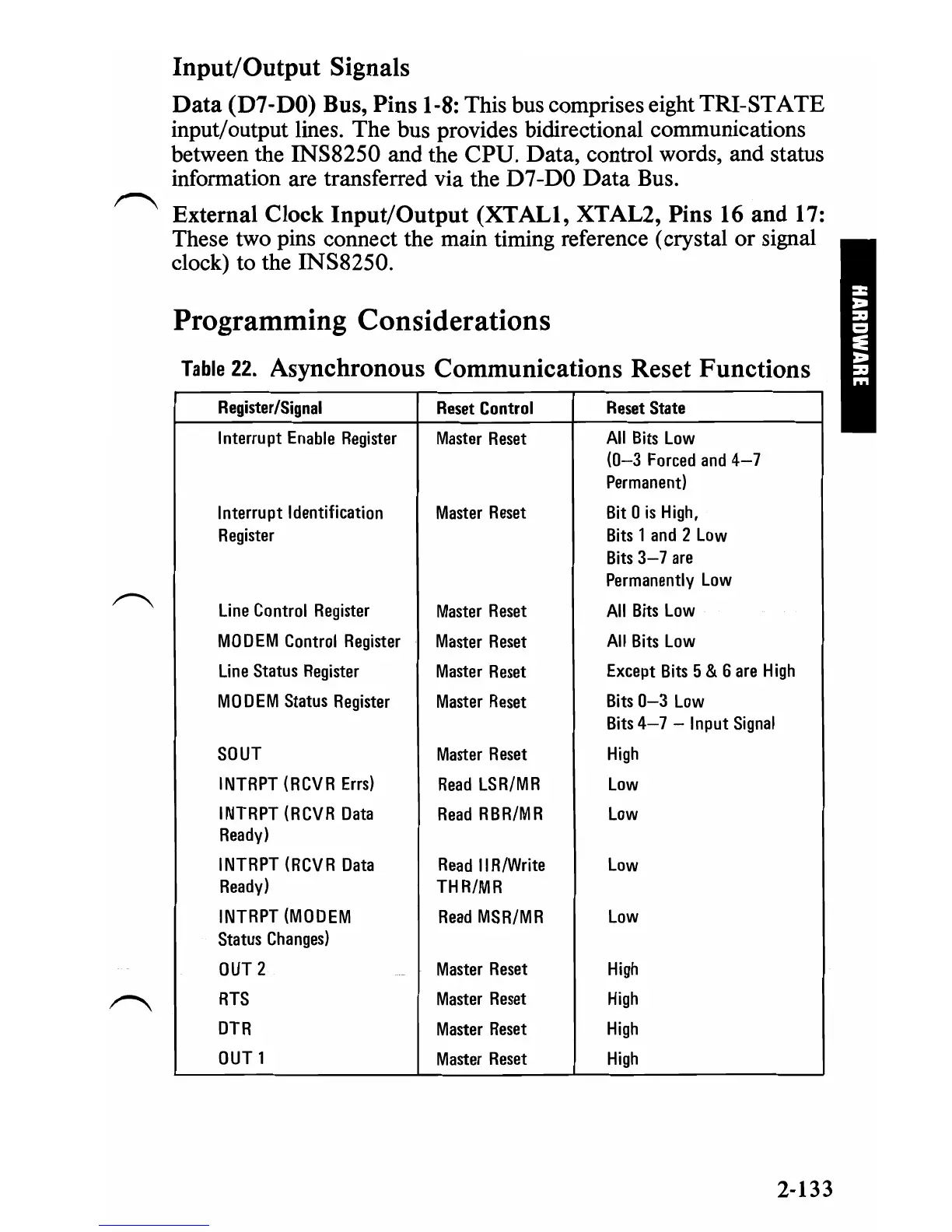
Programming Considerations
Table
22.
Asynchronous Communications Reset Functions
Register/Signal
Interrupt
Enable
Register
Interrupt
Identification
Register
Line
Control
Register
MODEM
Control
Register
Line
Status
Register
MODEM
Status
Register
SOUT
INTRPT
(RCVR
Errs)
INTRPT
(RCVR
Data
Ready)
INTRPT
(RCVR
Data
Ready)
INTRPT
(MODEM
Status
Changes)
OUT
2
RTS
DTR
OUT
1
Reset
Control
Master
Reset
Master
Reset
Master
Reset
Master
Reset
M
aste
r
Reset
Master
Reset
Master
Reset
Read
LSR/MR
Read
RBR/MR
Read
II
R/Write
THR/MR
Read
MSR/MR
Master
Reset
Master
Reset
Master
Reset
Master
Reset
Reset
State
All
Bits
Low
(0-3
Forced
and
4-7
Permanent)
Bit
0
is
High,
Bits
1
and
2
Low
Bits
3-7
are
Permanently
Low
All
Bits
Low
All
Bits
Low
Except
Bits
5 & 6
are
High
Bits
0-3
Low
Bits
4-7
-
Input
Signal
High
Low
Low
Low
Low
High
High
High
High
2-133
 Loading...