5-1/4" Diskette Drive
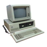
The IBM
5-1/4"
Diskette Drive is a single sided, double density, 40
track unit. The Diskette Drive has a formatted capacity
of
163,840
bytes, and
is
capable
of
reading and recording digital data using
Modified Frequency Modulation (MFM) methods. User access for
diskette loading
is
provided by way
of
a slot located at the front
~
of
the unit.
The Diskette Drive
is
fully self-contained and requires no operator
intervention during normal operation. The Drive consists
of
a spindle
drive system, a head positioning system, and read/write/erase system.
When the front latch
is
opened, access
is
provided for the insertion
of
a
diskette. The diskette is positioned in place by plastic guides, and the
front latch.
In!out location is ensured when the diskette
is
inserted until
a back stop
is
encountered.
Closing the front latch activates the cone/clamp system resulting in
centering of the diskette and clamping
of
the diskette to the drive hub.
The drive hub
is
driven at a constant speed
of
300 rpm by a servo
controlled
DC
motor. In operation, the magnetic head
is
loaded into
contact with the recording medium whenever the front latch
is
closed.
The magnetic head
is
positioned over the desired track by means
of
a
4-phase stepper motor/band assembly and its associated electronics.
This positioner employs a one-step rotation to cause a I-track linear
movement. When a write-protected diskette is inserted into the Drive,
the write-protect sensor disables the write electronics
of
the Drive and
an appropriate signal
is
applied to the interface.
When performing a write operation, a 0.33 mm (0.013-in.) data track
is
recorded. This track
is
then tunnel erased to 0.30 mm (0.012 in.).
Data
recovery electronics include a low-level read amplifier, differen-
tiator, zero-crossing detector, and digitizing circuits.
All
data decoding
is provided by the adapter card.
The Drive
is
also supplied with the following sensor systems:
(I)
A track 00 switch which senses when the Head/Carriage
assembly
is
positioned
at
Track 00.
(2)
The index sensor, which consists
of
a
LED
light source and
phototransistor, is positioned such that when an index hole
is
,.-......,
detected, a sigital signal is generated.
2-110
 Loading...