Interrupts
One interrupt line
is
provided to the system. This interrupt is
IRQ4
and
will be positive active.
To
allow the communications card to send
interrupts to the system, Bit 3
of
the Modem Control Register must be
set
= 0 (low).
At
this point, any interrupts allowed by the Interrupt
Enable Register will cause an interrupt.
,...-.......
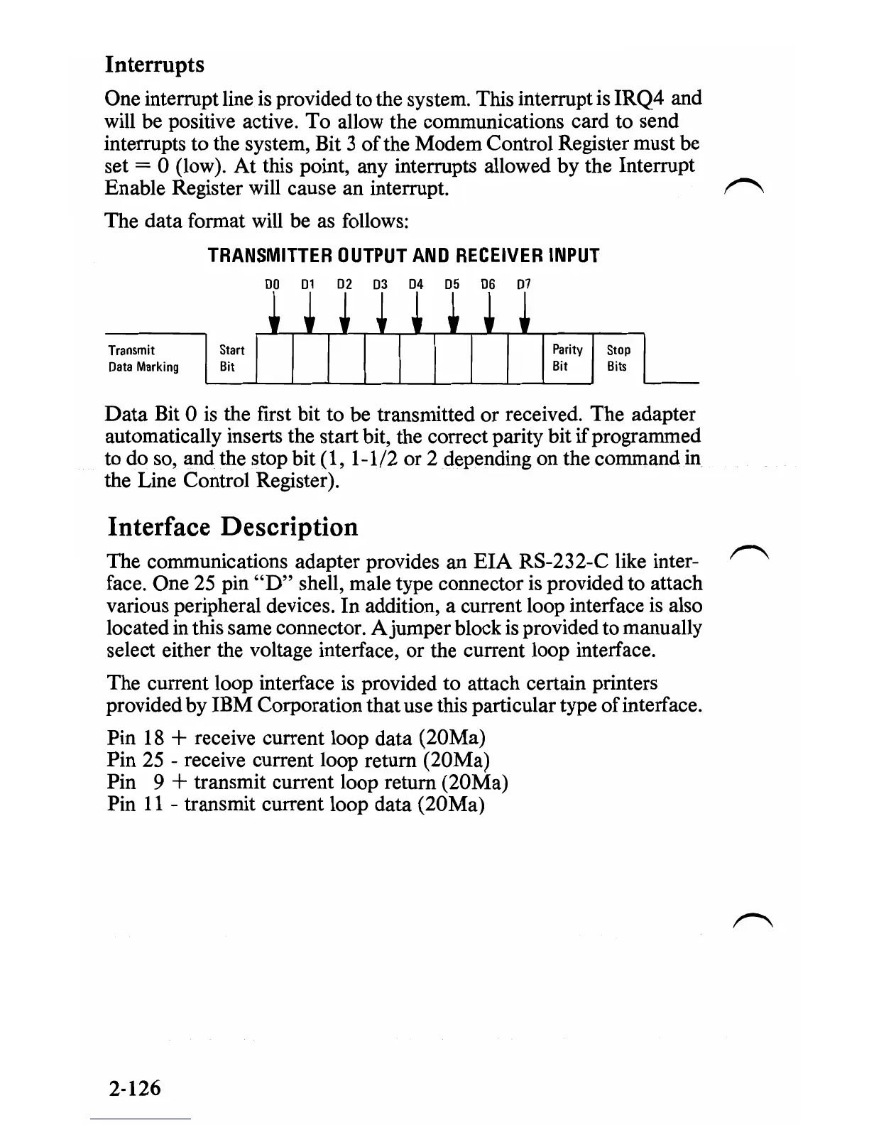
The data format will be as follows:
TRANSMITTER
OUTPUT
AND
RECEIVER
INPUT
00
01
02
03
04
05 06
07
Transmit
Oata
Marking
Data
Bit 0 is the ftrst bit to be transmitted or received. The adapter
automatically inserts the start bit, the correct parity bit if programmed
to do so, and the stop bit ( 1, 1-1/2 or 2 depending on the comm.and
in
the Line Control Register).
Interface Description
The communications adapter provides an
EIA
RS-232-C like inter-
face. One
25
pin
"D"
shell, male type connector
is
provided to attach
various peripheral devices.
In
addition, a current loop interface is also
located in this same connector. Ajumper block is provided to manually
select either the voltage interface, or the current loop interface.
The current loop interface is provided to attach certain printers
provided by IBM Corporation that use this particular type
of
interface.
Pin
18
+ receive current loop data (20Ma)
Pin
25
- receive current loop return (20Ma)
Pin
9 + transmit current loop return (20Ma)
Pin
11
- transmit current loop data (20Ma)
2-126
 Loading...


