The user must first begin the conversion by an
OUT
to
address x'201 '.
An
IN
from address
x'201'
will show the digital pulse
go
high and
remain high for the duration according to the resistance value. All four
bits (Bit 3-Bit
0)
function in the same manner, their digital pulse will all
go
high simultaneously and will reset independently according to the
input resistance value.
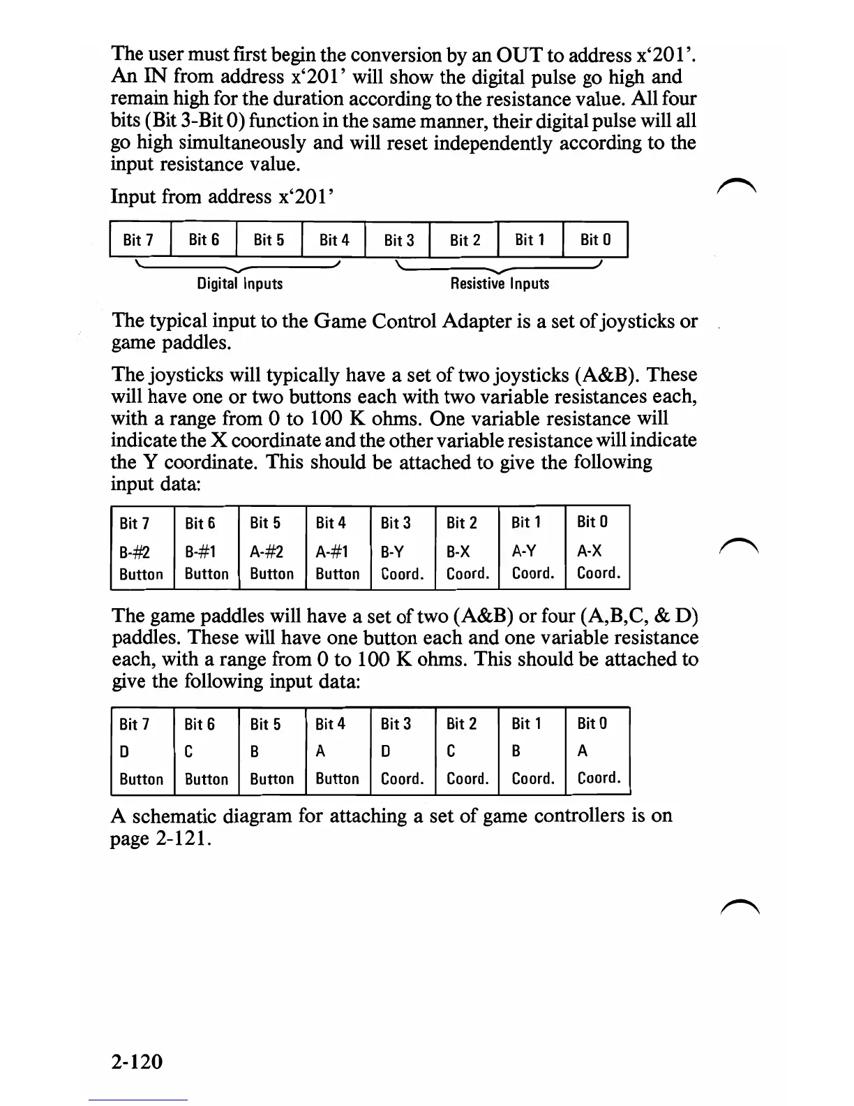
Input from address
x'201'
Bit
7
Bit
6
I
Bit
5
Bit
4
Bit
3
Bit
2
Bit
1
Bit
0
,
\
I
'"
Digital
Inputs
J
Resistive
--
Inputs
The typical input
to
the
Game
Control Adapter is a set
of
joysticks
or
game paddles.
The joysticks will typically have a set
of
two joysticks (A&B). These
will have one
or
two buttons each with two variable resistances each,
with a range from 0 to 100 K ohms. One variable resistance will
indicate the X coordinate and the other variable resistance will indicate
the Y coordinate. This should be attached to give the following
input data:
Bit
7
Bit
6
Bit
5
Bit
4
Bit
3
Bit
2
Bit
1
Bit
0
B-#}.
B-#l
A-#2
A-#l
B-Y
B-X
A-Y
A-X
Button
Button
Button
Button
Coord.
Coord.
Coord.
Coord.
The game paddles will have a set
of
two (A&B) or four (A,B,C, &
D)
paddles. These will have one button each and one variable resistance
each, with a range from 0 to 100 K ohms. This should be attached to
give the following input data:
Bit
7
Bit
6
Bit
5
Bit4
Bit
3
Bit
2
Bit
1
Bit
0
D C
B A D C
B A
Button
Button
Button
Button
Coord.
Coord.
Coord.
Coord.
A schematic diagram for attaching a set
of
game controllers is on
page 2-121.
2-120
 Loading...